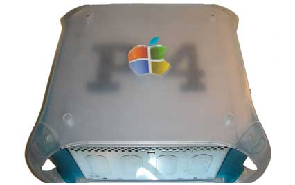
P4 Hackintosh

I thought this would be a fun first project. I have always enjoyed making something into something it was never intended to be. What could be more fun that doing it with computers. On one hand it’s the warped offspring from 2 different worlds. But on the other it could be seen as the common ground uniting them. I don’t believe that personally, I think the hate mail will start with the mac enthusiasts on this one. But that’s kind of the fun part here…
Overview:
All the materials for this project are easily available, some basic skill is required to use the power tools and make and take measurements. Costs are moderate on this project because I built this out to be a relatively good performing system (casual lan party capable even). I am sure this same rig can be made for substantially less if you are good at scrounging up parts.
This being my first public project I want to really stress safety and discourage those that don’t have practical tool skills from trying this project.
Any who. on to the part list for this build.
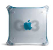
The old, busted, and lonely Mac G3:
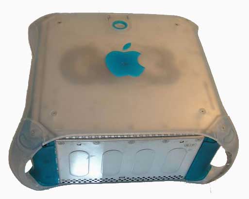
We chose the classic green G3 case for a few reasons. First and fore most, it has to be one of the most recognizable Mac’s ever made. Secondly there are thousands of this model in surplus storages, and on eBay. They are relatively cheep and parts are very available for these models so getting extra parts to get creative with is no problem.
We got ours from the University of Utah Surplus and only paid 25.00 for it. It was a complete and working system, but we gutted it before the project started. We see these in varying condition on eBay for 15.00 – 90.00
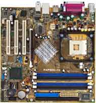
A new micro ATX form factor motherboard:
We used the asus P4P800-VM in this build, we chose this because it’s a really quite descent motherboard and supports a fairly high performance rig, and is definitely good enough for gaming. Now we had this board just laying around, but it sells for under 100.00. Other micro atx motherboards will work just fine so long as they match the standard case mounting hole pattern.
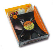
One New 120mm case fan:
One major challenge once we got this all together was cooling. The old Mac CPU runs much cooler than the new P4 we dropped in. This becomes a problem especially if you are running the newer Intel Prescott CPU. So we upgraded the 120mm case fan to a newer high performance main vent fan by Thermaltake.
We also found that a pci slot cooler fan was very helpful under the higher end video cards and even just to enhance the amount of air actualy moving in the case.
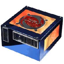
New power supply:
We went with a new power supply to support the Prescott’s power grubbing needs, as well as our new ATI video card. The Ultra X-Connect 500-Watt supply we chose also helps support the higher airflow we need with the air circulation in the case, and also acoustically is fairly quiet. The case is actually really well sound insulated, and we were able to get away with a little more noise on this as it’s a cosmetic mod. Finally we chose one of the new modular cable based power supplies just for that reason. Modular… Mmmmmm modular…
All the other main system goodies:
Hard drive, video card, ram etc… if you make this. Its your choice. We used just some simple off the shelf goodies. Western Digital SATA 80 gig drive. DVD-RW and a ATI Based video card. Inserting the components into a computer is really the most basic part of this build out, we will be concentrating on the modifications the case requires to make a system work and not the how to buld a computer 101 aspect. The flavor(s) is up to you.
Optional Parts:
Optional Parts for this project would be for further case appearance customization. Lighting, logos, and color can all be modified if you need. Some additional parts we required were:
2 peices of plexi or acrylic 4″ X 4″ X 1/4″
2-6 led arrays powered off the internal power supply
The external of the case will not need to be modified very heavily. You can save some time by stripping the case down to basics before you start into this project. in later sections we will be focusing on case lighting, something I don’t think the original designers of this case ever had in mind, but it really adds alot.
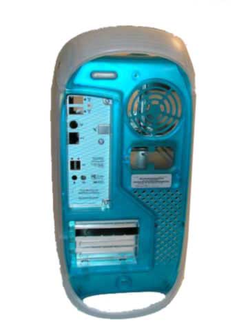
Items that need to be modified front on the rear of the case.
1. The back panel will need to be modified to fit the standard motherboard IO shield. 2. Fortunately the power supply will easily swap out with a newer model. Three of the four screws for mounting the power supply fit perfectly, good enough for invent geek and government work. 3. Due to the placement of the onboard audio I also found I had to cut some of the plastic of the case away. This is dependant on the motherboard you choose
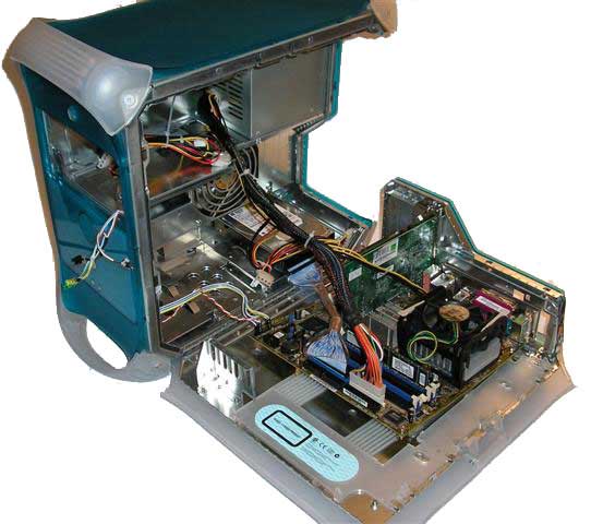
Just a shot of the case from another angle. In the four corners of this case later we will be adding some LED’s for lighting and effects. We chose a single color, but I have seen some real sweet USB based LED controllers out there that could make it more geek worthy….
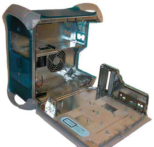
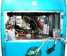
The interior of the case will require some more modification. Nothing a 3rd level geek couldn’t pull off.
The motherboard mounting plate and plastic panel that tensions the latch to the case. Also note the Motherboard mounting posts; they are about twice the height of a normal PC case’s mounting posts. The plastic plate will need to be modified to allow the new posts to be mounted.
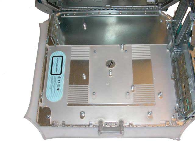
The motherboard mounting plate with the plastic panel and the existing motherboard mounting posts removed. I just used a pair of pliers and snapped them out. We did have one that deformed the panel a bit too much. There are many methods to fix something like this; we choose the most simple method, a big hammer. With the case nice and clean we can move on to mounting the posts.
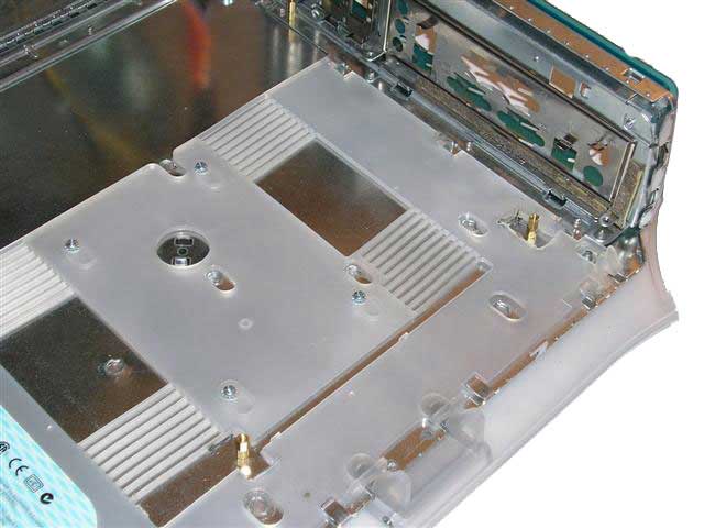
The motherboard mounting plate with the plastic panel reinstalled. And the new mounting posts installed. I found there is a difference in the heights of the old posts and the new one I used. I had to double the posts I used up to double the height. Also look closely to the right most post. We had to cut a large space out for it as the whole of the plastic panel moves when the latch is operated.
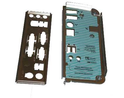
The original IO shield. And the one that came with the motherboard. They are obviously very different. The standard pc case IO shield is meant to just “Pop in” where as the Mac IO shield is a screw in model. Unfortunately as you can see the motherboard accessories holes in the new IO shield is not even close to the original Mac one, we had to modify this quite heavily, first we measured the space we would have in the Mac case for the new motherboard. The method we used for placement of the mother board was to mount the video card into the mother board, and place it into the case via the appropriate slot in the back of the case.
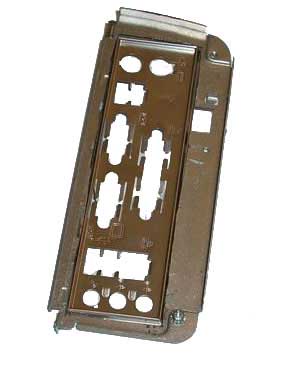
The original IO shield modified to fit the new IO shield that came with the motherboard. Turned out the old adage measure twice, cut twice applied here…. the top of the panel was off actually about 1/2 an inch. so after some modification, dinner, and cursing…. we got it fixed. The trade off, we lost the onboard sound behind some structural components of the case its self. But in the end that was just fine with us. The sound on this board was a disappointment, and we used a sound blaster card in stead.
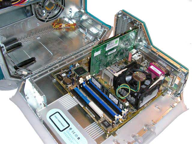
Test fitting the motherboard into the system. I mounted the video card into the motherboard to verify the PCI/AGP slots alignment with the case. And the IO shield finally fit right. Remember kids. Measure twice cut once is a great idea when working something new. It saves time and keeps a man off the couch for the night for swearing at a stupid computer…..
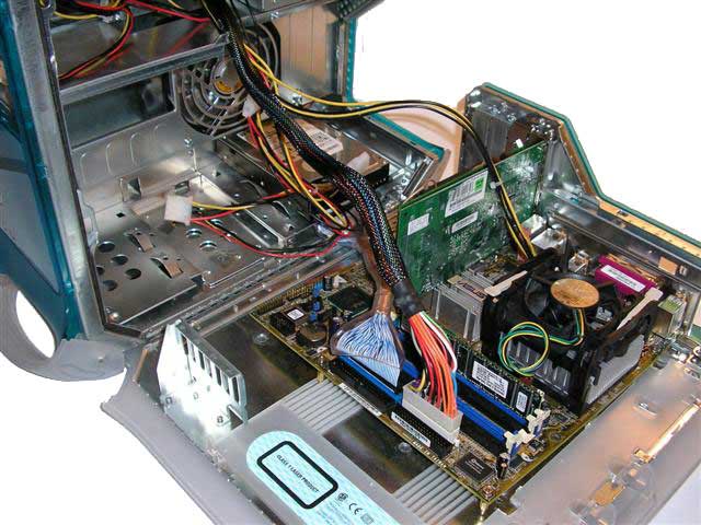
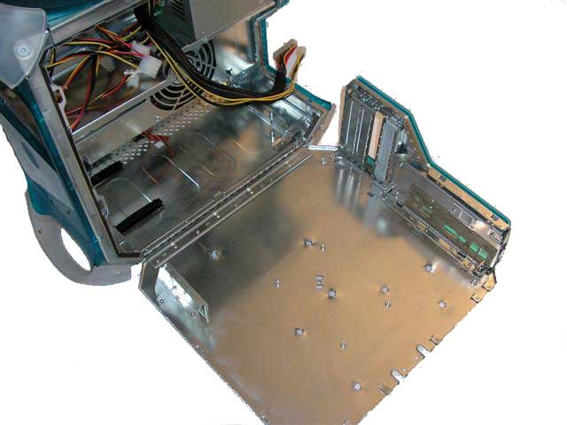
Test fitting the power leads into the motherboard. On of the cool points of this case is the easy open panel. The first power supply I mounted didn’t have a long enough power cord, so I use another one, alternatively I could have used a ATX extender cord.
Mounting the hard drives and running the cables for it. I was able to find some 8 inch copper shielded, rounded cables at CompUSA of all places that fit quite wonderfully. Zip ties are a geek’s best friend some times. And other times they can in and of them self lead to the inevitable downfall and destruction of man kind. Use them at your own risk. and don’t ever ever shinch one down on your finger to watch it turn blue….. Um….. Just don’t do it.
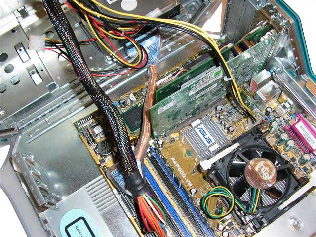
One more view, almost done with the internal mods. Now that wasn’t so hard was it…
Motherboard clearances are real close to the case and power supply. But close enough for us. If you use zip ties you can place the cables where they won’t get in the way of the case opening and closing, or get in the way of important components, or restrict air flow. Other wise you will need to use the “peek and prod” method to close the case. As one of the main reasons for this mod is the cool factor of the cases easy access ability we probably would rather use the zip ties.
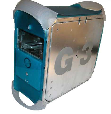
The case with the sides off. The G3 logo is really easy to see. The G and the 3 are actually just really big, thick, heavy duty stickers. Now why they didn’t do something that would sound much more economically motivated like just silk screening on the logo is totally beyond me…. Saving costumers money is apparently not a super high priority. but hey it makes my life easier…
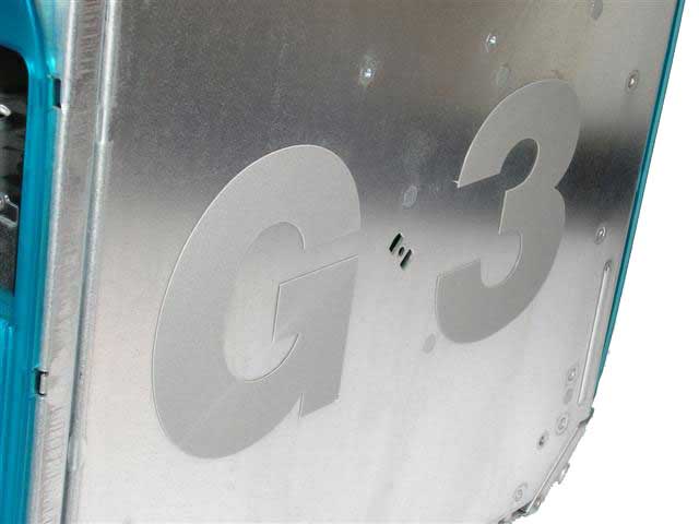
Pill the stickers off; I had to use a razor to start them. Just pill up a corner and off the come. It looks like the adhesive was really cheep. But it did leave some residue on the case. and as we want our P4 to look as good as the G3 I decided to clean it off…. I just used some good old normal every day flammable Goof Off solvent to get it nice and sparkly.
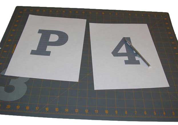
I printed on my computer a large “P” and “4”. I tried a few different fonts and sizes to match the style of the ones on the original case. Finally I think I just settled on times new roman. Use a razor to cut the letters out watching out for fingers and small animals in the process. Razors are mysterious and fascinating devices, they seem to spontaneously attack users and near by on lookers for no reason. For this reason we have decided that razors are inherently evil, and should be watched closely in regards to the whole “world domination thing….”
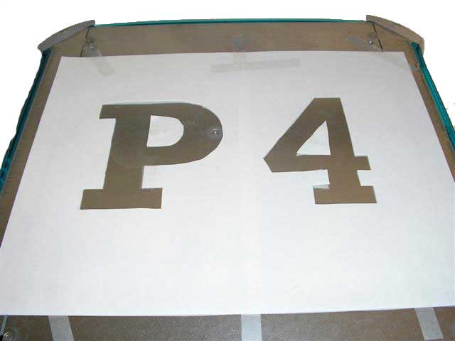
Take the paper cutouts and tape them to the case. Carefully spray paint the stencil you made and remove it once dry. You can use rubbing alcohol or lighter fluid to clean any mess-ups with a q-tip. Do this out side as the fumes from this are very toxic and will most likely result from indoor use in a -3 modifier to geek intelligence.
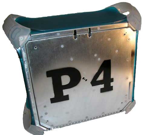
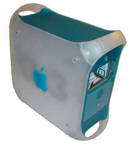
The end result with the new sides. Now it doesn’t look as good as the original…. we know…. but I don’t care. When you put the sides back on it looks real good. You see I don’t have any formal training in ghetto paint techniques…. I am happy with the fact I didn’t get it in my eyes and it looks that good.
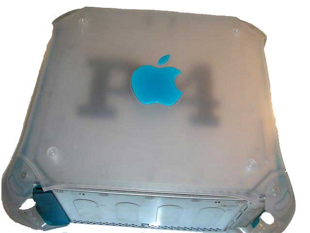
Plastic side put back on. Looking good me thinks. Real good. In fact I wonder if ole Steve Jobs is looking for some one to design the new G6 when it comes out….
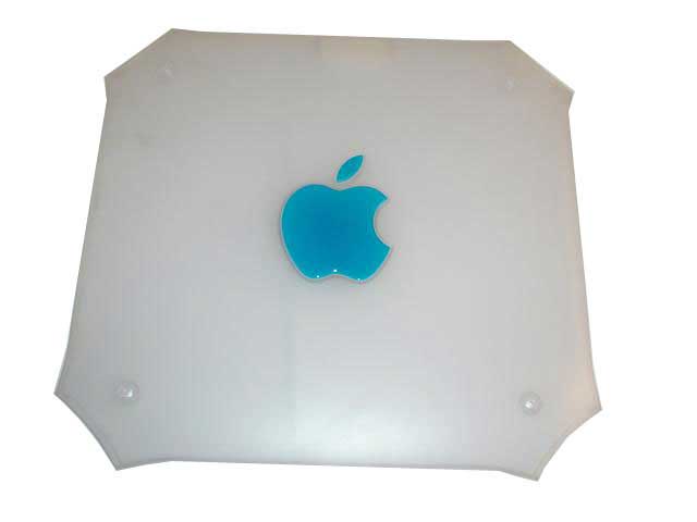
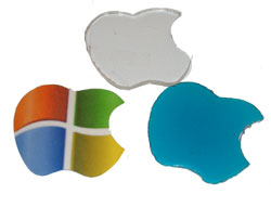
A closer look at the plastic sides. I wanted to pay homage to the original Mac case as it definitely has style. At the same time as tainting it. Now I know the world of computers if full of band campers. And that going ahead with this would piss most camps off at me. So I did. I decided to make the logo into a little more Microsoft feeling logo. We all know Steve and Bill are real good buddies and all.
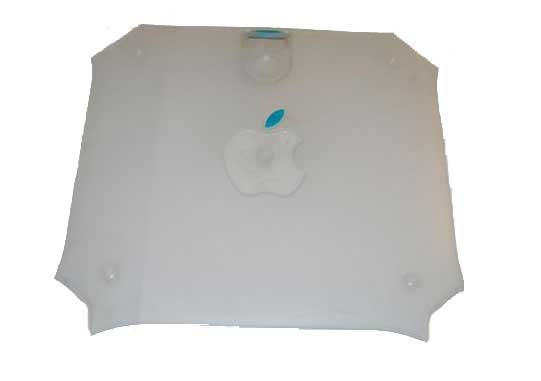
First things first…. removing the original apple logo from the case. Remove the plastic apple from the case with a flat head screwdriver, it just pops right out. don’t throw them away as we are going to use them to template a replacement.
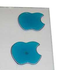
Trace the apples you have removed with a marker on to some plexi glass. Remember any cutting needs to be to the inside of the line.
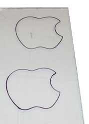
The tracings we made. We used a dermal tool with the plexi cutter blade to cut out the patterns. Dermal tools are really quite useful to the geek. I keep the standard geek tools all on my belt, my leatherman mulitool, my PDA, cell phone, or PDA cell phone; And of course my prototype fusion power source for charging my cell phone / PDA. Now if only dermal would get on the ball and make a really miniaturized version of the dermal tool I would have one of those also.
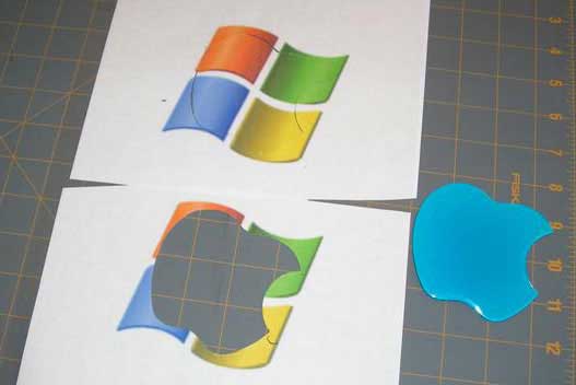
I sat down at the computer and cleaned up a Microsoft logo I found on Google image search. Then blew it up, printed it out and used the old apple logo to trace and cut it out. I also made a logo with Tux, but that’s to socially acceptable…. so uncle bill it is. Once again… use caution with those razors, they just can’t be trusted.
The old apple logo, the new Microsoft apple, and the plexi apple all together. I sanded the plexi apple down to match the taper the original one had, then I used a torch to heat the plexi up and gloss it over so it’s not fogged. Pen torches are really cheep and useful when geek moding. I need one of those for my belt also now that I think of it. Usually I just modify lighters to shoot a 2-3 foot flame… nah that’s definitely still cooler.

I used a couple drops of super glue to affix the new apple to the case. As the case is really kind of plane 2/3 tone…. the color of the MS logo is really bright and eye catching.
Experiments in case lighting:
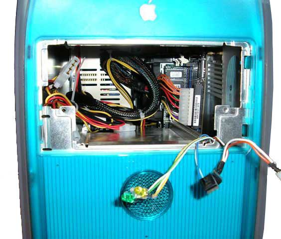
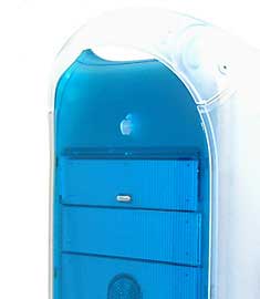
Now that we have main mod of this project buttoned up, we needed to do some testing to determine what type of lighting we would apply to the case it’s self. In the pic to the right you can see one of the handles on the case. I thought it would be cool to light them each according to the corresponding colors of the Microsoft logo, I did some testing on this but in the end I abandoned the idea as it looked great from one side of the case and was reversed on the other. I really liked the handle lighting, but as the main focus of this mod is the fact it was a Mac converted to a pc I felt that it distracted to much from the logo I had already created. Now if I had left in the original Mac logos using blue LED’s in the handles and in the side panels would have been totally pimp.
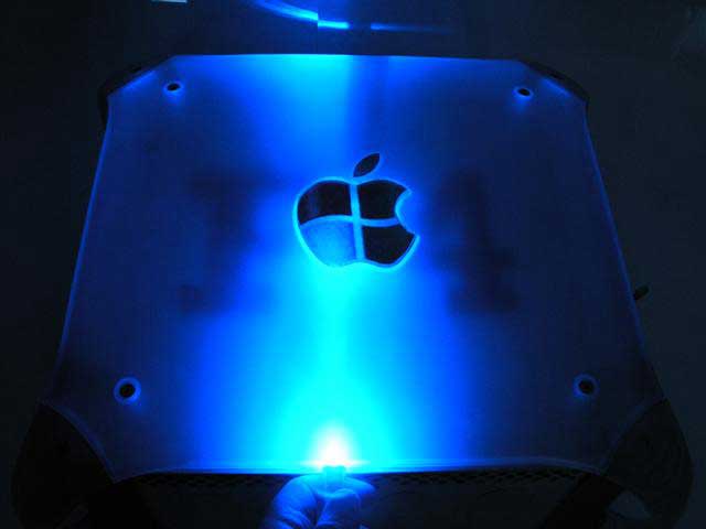
I have one of those crazy Led flashlights, so I drove my self down to the local radioshaq to see what LED’s they had (personally I don’t like to use radio shack for my electronic component needs, there far to over priced… but I wanted to try to get this done today) I got some high bright red, green, blue and yellow. I just dropped them one at a time in to my flashlight and placed it in various places of the case so I could get an idea of the effects I could achieve. Here to the left I was playing with the blue. The interesting thing with the blue LED’s is just how bright they are. One led was able to really light the entire side of the case up.
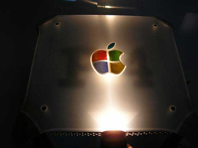
So in the end my trip to radio shack was in vain, after finding my old mag light I decided a white light was definitely the way to go with this project. So I moved the light around and decided on mounting it in the bottom center of the case, it really shows off the P4 and the logo very well. Good bright vivid color also. I would have liked to try the UV LED’s with some reactive materials behind the logo to see if I could get it to glow with some cool effects. This lighting was cool in the end, but I think I want to get some EL materials and cut out the colored sections with an appropriate color and make just the logo glow with some accent lighting for the P4 under it. But that’s the problem with me…. too many ideas and not enough time.
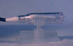
I choose Sunbeam Technologies LED Laser Beams for the lighting. I was surprised to find that there are no lasers involved in any of their products at all… I suppose its just the marketing “Cool Factor” that allows them to call anything a “Laser”, but they do make a good product. Cheep, easy to install, and they power off your power supply so they are real easy to install and power. Adhesive bottoms, and they swivel to allow you to place them any where, and they have a spotlight and flood lenses for the led as well. There are convenient holes in the case for the power. I did have to cut the power wire to get it into the case as they have the standard 4 pin power adapter on them, but a little heat shrink tubing and there as good as new.
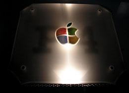
The finished project, I really think it shows off the logo’s colors very well. I recently took this to a LAN party with about 50 people, as the lights were dim in the room we were playing in the case really stands out. It’s bright, and surprisingly colorful, and confuses people right from the get go. So I would have to say the project was a success. If I had gone all out with blue lighting it would have been more of a naissance to me and other gamers and there for would have lost alot of the cool factor. Now if I can just make the case about 45 Lb Lighter I would be really happy.
Final Thoughts…
This has been a fun first project, and while the technical aspects of this are not challenging as some of the other projects I am working on right now it still has been rewarding. One thing I learned is that this is not a every day project, in the end I think I spent about 800.00 or so… so my first final thought is to watch the bank account on this project. From sanding materials, plexi, lighting, to cutting disks, it all snuck up on me. Other thoughts I have are more cosmetic, let’s face it, being restricted to a micro ATX motherboard is about enough to make any
power hungry person go crazy. www.sunbeamtech.com has a really neet product called the Chameleon Lighting Controller, this uses groups of leds (red, blue, green) to mix colors real time via a control panel that mounts into the standard 5″ drive bay. Also as the case is just so heavy i would like to have tried some of the unique cold cathode tubes that either have the lightning effect or the water looking effects as well. Mounted in the edges of the case it would look real cool. But then you need a bigger power supply, put out more heat and have another set of challenges to over come. Heat is still a concern in and of its self, but I figure in a month I will just burn this any way…
If you get really ambitious air flow can be increased, and there for cooling to a point. I believe this case is a very good candidate for water cooling, the 120mm case fan it already has with a blower port out the back can help this with out much modification. After all, the front of the does have some extra space under the drive bays.
Any who… there are other fish to fry out there, and other warped ideas to see to some end. And although I could woulda coulda shoulda to the end of time, I am really happy with the way this turned out, and I submit my ideas and thoughts to you all.
Until next time, remember to see how far you can push the envelope.
Related Posts


No Comment