Overview:
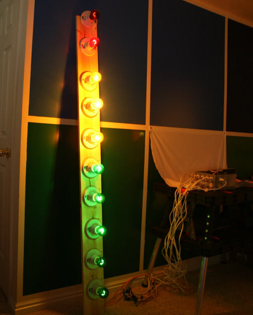
So this is kind of a fun project overall. The real star of the project is the control box that is a small elegant control system with easy to use plug outlet type connections. We have 12 isolated outlets on this control box for all sorts of fun larger future projects we are doing, but this can be scaled to any number of outlets you may need with ease. So we wanted to demonstrate simply the projects ease of use with a project that has a little eye candy. And so the giant vu meter project was born. The vu meter its self is actually simply a bunch of light bulbs with a plug outlet to each and a driver circuit based on the LM3915 IC. We have some basic diagrams of the circuit design and pictures of the interface. But ultimately this can be easily interfaced with just about any microcontroller platform for any number of possible ideas you may have.
Plug Outlets:
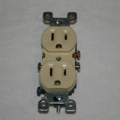
Here we have one of the more important components of this build. It is important that this $.59 component is the correct version of it or you will seriously limit your ability to do this build. When looking for the plug outlets you will use for this build it is critical that you find one that has break off tabs on the sides of it to separate the top and bottom receptacles. We will only do this to the Hot (black wire) side of the outlet as we will chain the neutral (white wire) between outlets.
Project Box:
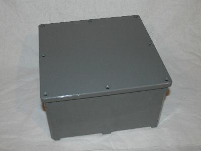
For the project box we actually found a plastic electrical box at our local home improvement center. These are often used in applications where you need a electrical junction of some type in a outdoor application that is weatherproofed. These boxes are all weather proofed and have a nice seal. They will set you back about 25.00 but I love the heavy duty design so for me it’s worth it.
Solid State Relays:
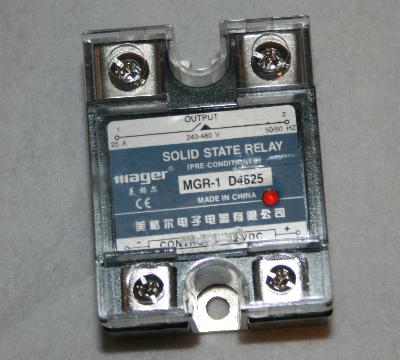
Solid State Relays have become one of my new favorite components. These relays are extremely fast switching, highly reliable, rugged and even opto-isolated to protect your circuit should you accidently get your wires crossed. If you buy these stateside you will pay up to about 50.00 each! But if you buy them on ebay, and if you can wait a couple weeks you can get them for about 10.00 with free shipping directly from china. Now can you use regular mechanical relays? Of course, but I found in early testing they would break after a couple days of heavy use…
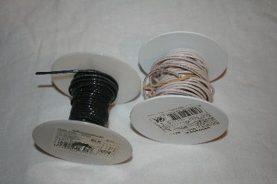
Wire:
Fairly simple component, but its good to be crystal clear about it I guess. You will want to use a 14Ga solid copper wire for this project. Stranded wire will not work safely so don’t use it. I also recommend using the appropriately colored wires to keep everything straight.
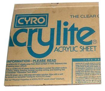
Acrylic:
So there is no mystery that I love working with acrylic (plexy) when doing my projects. It looks slick, is very strong and most importantly it is easy to work with. For our project here we will use 2 – 12” square sheets of 1/8th” thick acrylic that we will use to mount the relays in easy to maintain modules.
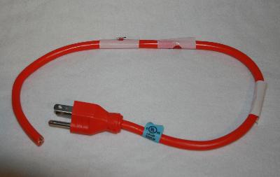
Power Cord:
For this build we will be centralizing power distribution through this control box. So obviously we need a way to get power into the box. I stopped at our local home center and purchased a 10’ extension cord for 3.00 and just cut a 2 foot length off so I had some play inside the box.
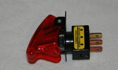
Power Switch:
So this box will look rather plain overall when its finished. So I wanted at least a good looking illuminated apocalypse style switch to both indicate the box was on but also to turn on and off the driver circuit inside. If you want an extra step for safety you can use an additional relay in line with connected to the power switch to disconnect power to the entire box… but for my needs it just controls the driver circuit inside.
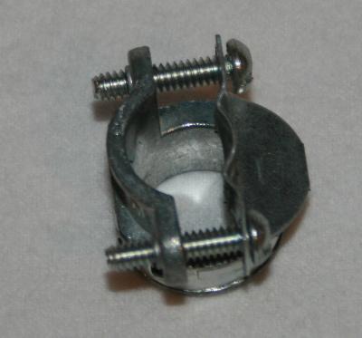
Cord Restraint:
So these little cord restraint clamps are invaluable! They cost 2.00 each and when this project is dropped, or kicked, or someone comes along and trips on the cable, or maybe you have it connected to your giant robot of doom and it walks off to follow your commands while still connected… whatever it may be someday the cord will get yanked and you don’t want the internals connected to it trying to come racing out the hole with the cord. So this little clamp I totally recommend getting at your local home center or electrical supply.
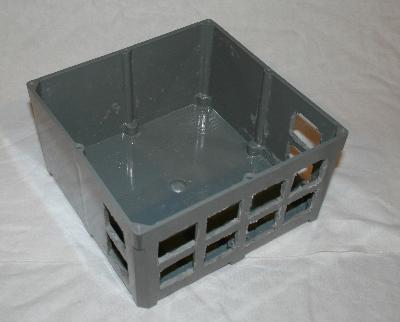
So step one in our assembly is to cut up our project box basically I just turned upside down the plug outlet and then marked out a grid for spacing. For the 12” project box we are using 12 relays and 6 outlets fit the space perfectly. Take care when cutting the holes out with your dremal tool that you don’t cut at an angle or you will have some grinding to do.
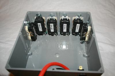
Next step is to attach the outlets to the project box using some screws and nuts. Depending on the type of outlets you are using you may want to consider attaching the ground wire before screwing them into their final place. With the outlets installed I recommend at this point you fill the gaps around the plugs with some silicone or hot glue to help keep out the local environment.
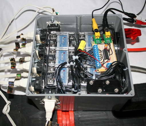
This is a great shot of how to do the wiring in this setup. So as pointed out earlier we will be breaking the tab off between the hot side of the outlet while leaving the neutral side of the outlet enact. The reason for this is so you can jump between the outlets with a small amount of wire. Make sure to keep this wiring clean and low profile while you set it up.
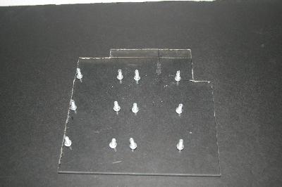
So next up is to create the base plate for the relays to be mounted to. Using a sharpie place the acrylic on top of the box and trace out the inside of the box to be cut out. Leave a ½ inch gap between the backs of the outlets and the acrylic for the wires to fit.
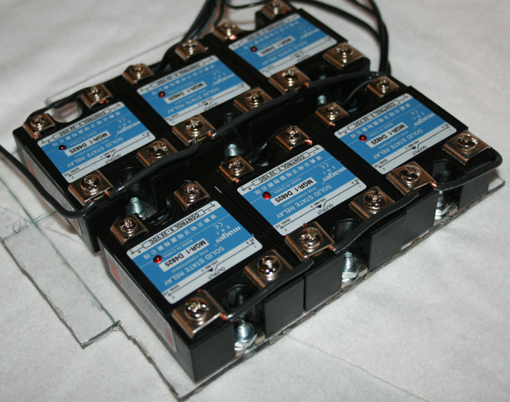
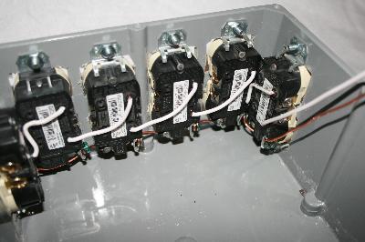
Here is an attempt to show the wiring of each relay board. We have some 22-24 gauge wire coming off the low voltage side of the relays to go up to the controller. In the front of the relays we are jumping the hot (black) wire between all the relays to keep the wiring clean and simple. We will attach the unused terminal to each outlets hot wire.
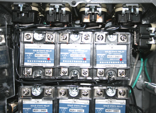
Here you can get an idea of the wiring from a top down view. We connected the bottom board to the bottom half of all the outlets and the upper board to the upper outlets for consistency and ease of access incase of any required maintenance.
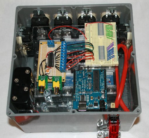
So here we are experimenting with layout for the controllers on the top level. You can see that our custom board for the vu meter, a breadboard and even the arguing all fit easily into the space remaining. In future projects we will do some control panel stuff with the extra space also.
So here we have a shot of the setup for first test. We used a 12v battery pack to power the vu meter board, though if I had a 110 to 12v dc power supply board I would much rather use that.
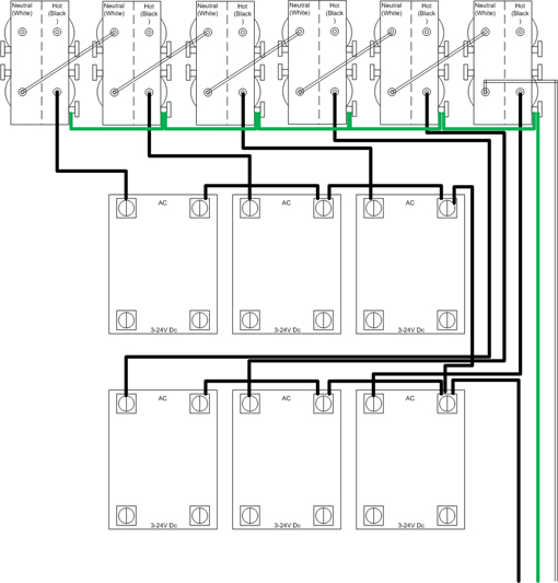
Here is the wiring diagram for the build. I hope it clarifies the layout and wiring that the pictures were a little short on.
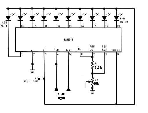
So here is the wiring diagram for a simple vu meter circuit. This is very easy to layout and setup for experimenting. If you want to see a close up of the board let me know and I will post some pics if you need them.
So here is a video overview of the project with a demo of it working. Lots of good advice in this video as well as some tips.
so… what do you think of this article? All InventGeek projects are funded out of pocket and we do our best to freely share what we have learned do you can do your own experiments and build on our work. This can sometime be a costly venture for us; this is why we ask for donations to help InventGeek grow. We ask only that you help and support our efforts.


It doesn’t appear to work as a VU meter at all. All the lights seem to flash in sync with the music but not in a graduated way toward intensity at the top. Anyway you can reduce the signal to actually see the the red and yellow lights NOT light up?
The video actually shows the problem of using a incandescent light bulb. The bulbs take so long to heat up and cool off, mixed with the samplings rate of the LM3915 would work a million times better with a LED based light bulb.