Analog Meter Clock
Intro
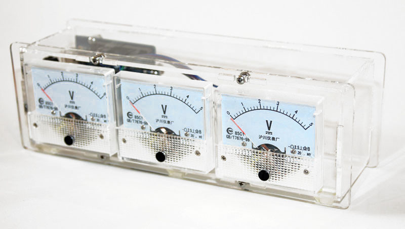
This is a fun little project I did a few years back that I thought was worthy to publish here. This project is an Arduino controlled analog meter clock. With its sexy acrylic chassis and retro look it’s a great addition to any bookshelf. Powered via the USB cable you can use a simple USB wall wart to power this clock and put it anywhere you need some retro style!
Case
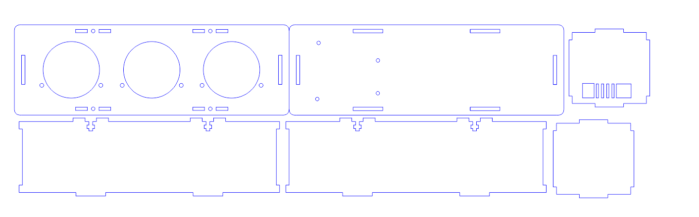
The case is made from laser cut .118 Acrylic. We used a clear acrylic because it plays with the light and the clear covers of the meters in a way we love! It also lends itself well to being used with lighting. As a fun variation you could also include some RGB leds into the chassis and use the PWM pins on the Arduino to make the chassis really pop! We will add this chassis to ponoko for anyone that wants one.
Arduino
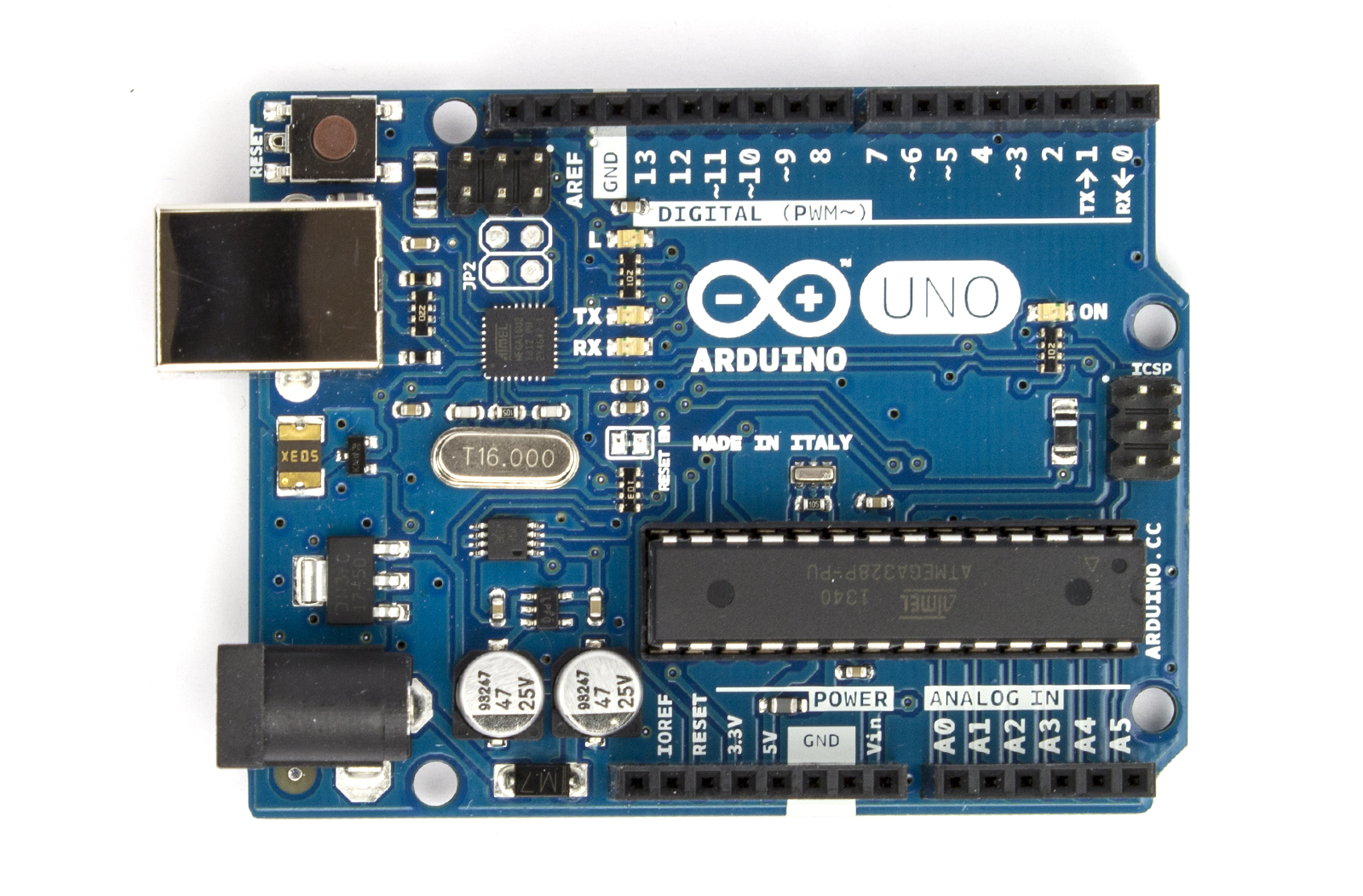
For this project you will want to use a current Arduino. Any Arduino would work, but if you’re going to show off your Arduino it may as well be shiny and new. You can find an Arduino here if you need a spare.
Adafruit RTC Board

Next you will need a real time clock module. These are great little gadgets and once set with the correct time they will run and run with their onboard battery. I personally like the model at adafruit, and for 9.00 its a good deal. Check out the adafruit wiring article for more info!
Meter
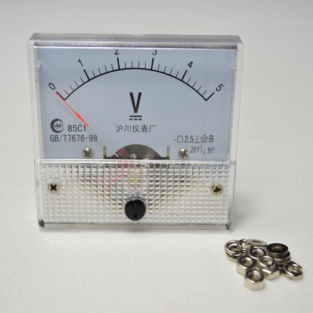
Next on our build list will be the meters there self. Just about any 5V panel meter will work just fine but if you can match the model we have pictured here it seems to be more responsive than other models we tried. Ebay is the best source we found so take a look around and see what you like.
One other thought, I personally prefer the look of the panel meters being factory stock, but you can simply remove the white shield inside the meter and paint it however you like. So if you need to have 12 points vs. 10 it’s easy to change up.
Buttons
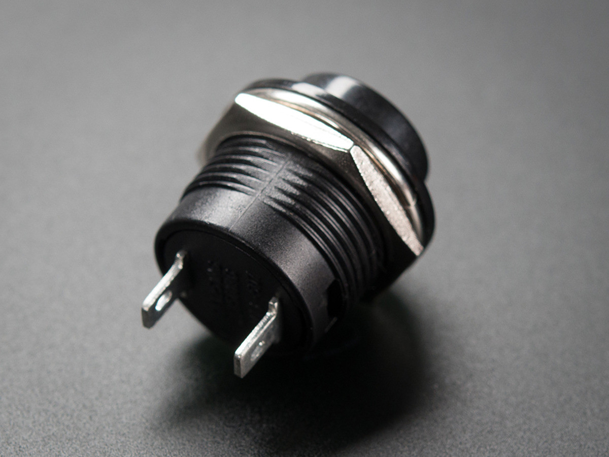
Finally we need our buttons so that we can manually change the time on the displays if needed. This really is an optional component in the build because once the real time clock module is set it will always remember what time it is with or without it being plugged into power due to its onboard battery. So it’s up to you, but if you throw in those RGB LED’s then perhaps you can use them to change the colors? lots of ideas! Get the same buttons we used here.
The Project Build

The first step in our build is to make sure we understand our meters. The meters are polarity sensitive. In other words the meter has a positive and negative lead that must be adhered to or your meters won’t work. In the picture above the left post is the Positive lead and will connect to the Arduino Analog pin corresponding to the meter display you want. The right Post is the Ground or negative lead. These can be chained together to simplify wiring and will be connected to the radio’s Ground Pin.
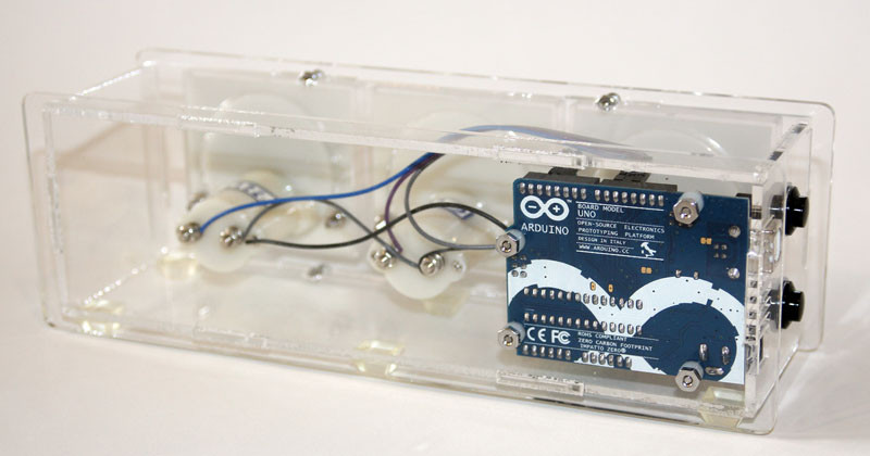
Here we have a view of the back side of the meters that will help you see how the wiring is done. We simply chain the ground posts together to simplify our wiring.
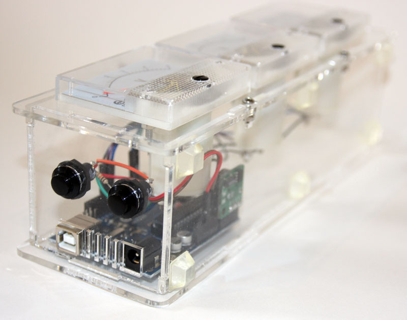
Here we can see our optional buttons mounted into the case. By using low profile buttons we don’t have to worry about them hanging out of the side of the chassis and hurting the clean look of the clock.
Finally a video of the clock running. This is a super simple project but it has some real style! Give it a try and please share this project if you think its cool!
Chassis:
Code Example:
Arduino.pde
Related Posts
6 Comments
The code on this for Arduino is not linked – can this link be fixed? (please!)
Arduino.pde file is not linked :o(
Hi, thanks for share this nice project, and will build a panel clock
I am new with Arduino, is it possible to share some drawings
from the connected wires between the Arduino and the panel meters.
Thanks,
..woher bekomme ich das Arduiono-Sketch File? (Arduino.pde)
Danke
Nice project too bad the code (.pde) is not linked. Anybody have it?
Make this one instead:
https://www.instructables.com/id/Analog-VU-meter-and-Clock-Arduino-Powered/
Works fine, and combine it with this:
https://www.instructables.com/id/Arduino-DIY-Analog-Thermometer/
And you get a very nice analog unit 🙂