Micro Monitor
Author: Jared Bouck
Project Cost: $20.00 – $25.00
Est Construction Time: 1.5 – 2.5 Hr
Required Skill Level: You’re going to need to be able to solder…
Overview:
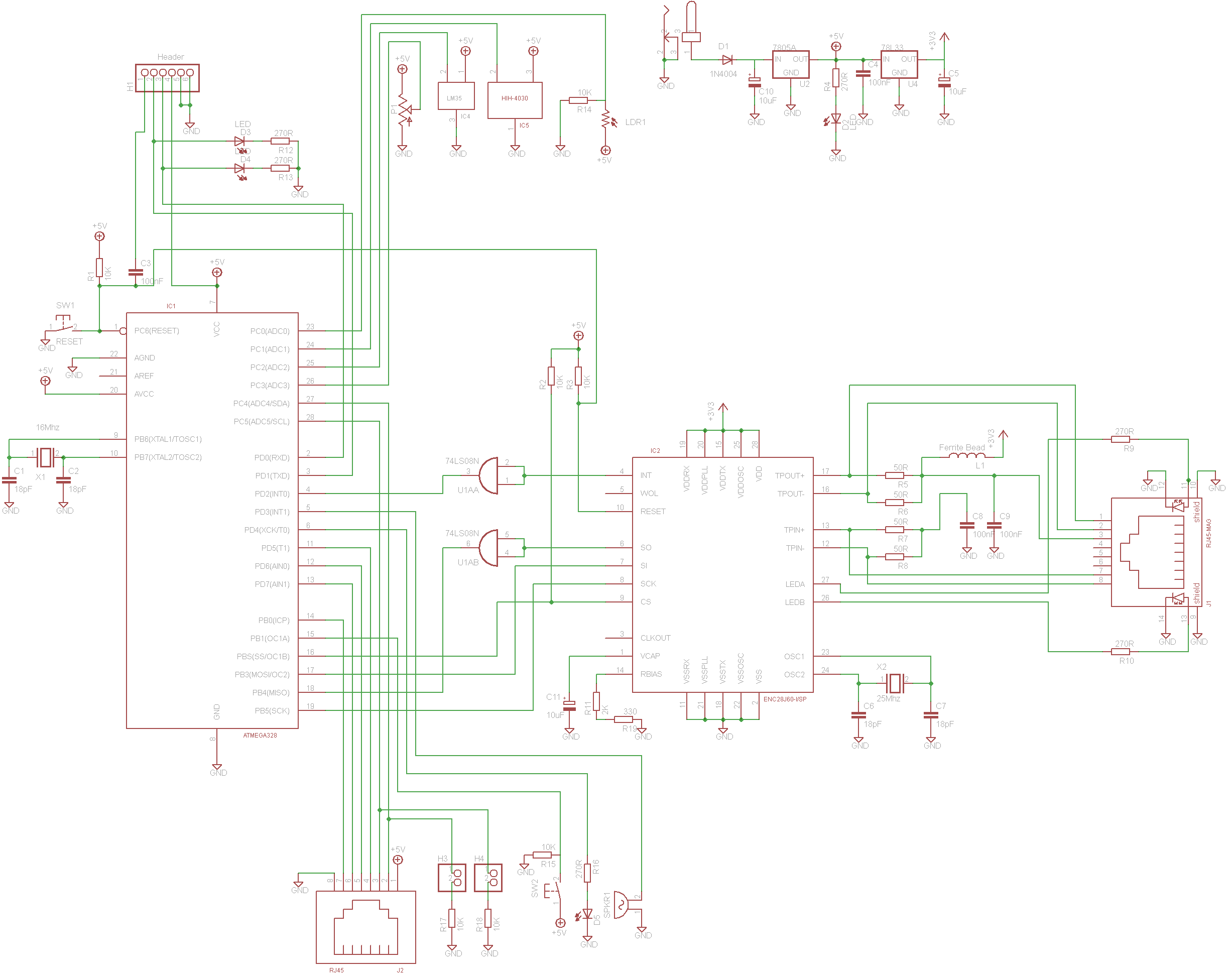
This is a project I did a few years ago that I am dusting off for all you makers out there. This project is titled the Micro Monitor and it is a simple but powerful board. The core of this project is an ATMEGA 328 running the Arduino platform and an ENC28J60 Media Controller chip that creates a simple to use Ethernet capability for this board.
In addition the board includes a small suite of sensors that have been added to a tab on the side of the board so that the onboard sensors are more accurate, including a Temperature sensor, Humidity sensor and Light detecting Resistor. We also added in a push button that can be configured for anything you want (silence a audible alarm?), piezo buzzer, status led, two Jumpers with pull down resistors, a 10K ohm Potentiometer (used for tuning thermal or light sensors?) and an additional RJ45 Jack that is designed to connect to a multiplexer for even more expandability.
This is a very easy to build, hack and use board and we have included everything you need to build this yourself! Don’t be afraid to remove or modify any parts you don’t need or want to use.
***** If you like this and would like to see us put together a board order or Kits let us know in the comments below. If we get enough feedback we will get a production run ordered.
The Board:
At the bottom of the page you will find all the cad files for the chassis, eagle files for the board and example app code.
The board is roughly 2.5″ X 5.5″ and is almost entirely hole through components making it easy for the novice maker. The humidity sensor is the one Surface mount component but is extremely easy to add.
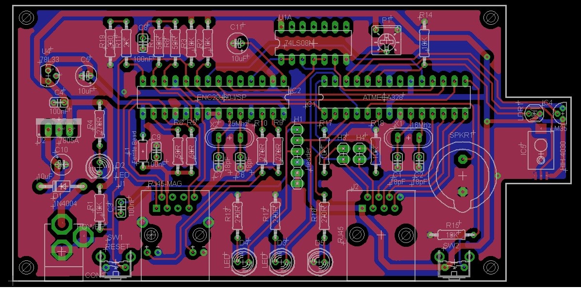

Board Etchings and Paths
Click the diagram above for a larger version.
BOM:
Bill of materials. This should be about everything. I have used and prefer both Mouser and Newark, but shop around for the best prices and substitutions.
| Component | Description | Part Number | Quantity | ID on board |
| Buzzer | PC Mount 12mm 2.048kHz | MULTICOMP – MCKPX-G1205A-3700 | 1 | SPKR1 |
| Capacitor – Ceramic | 100nF | NICHICON – UVR1A101MDD1TD | 1 | C4 |
| Capacitor – Ceramic | 18pF | MULTICOMP – MC0805N180J500A2.54MM | 4 | C1, C2, C6, C7 |
| Capacitor – Ceramic | 100nF | NICHICON – UVR1A101MDD1TD | 2 | C8, C9 |
| Capacitor – Electrolytic | 10uF | MULTICOMP – MCRH16V106M5X11 | 4 | C3, C5, C10, C11 |
| Crystal | 16MHZ | MULTICOMP – HC49S-16-30-50-70-30-ATF | 1 | X1 |
| Crystal | 25MHZ | MULTICOMP – MCRS025000F183000RR | 1 | X2 |
| DC Barrel Power Jack | 5mm jack, with a 2.1mm center pole | CLIFF ELECTRONIC COMPONENTS – DC10A | 1 | Con1 |
| Diode | 1N4004 | Y GENERAL SEMICONDUCTOR – 1N4004-E3/54 | 1 | D1 |
| Dip Socket | 28 pin | MULTICOMP – SPC15504 | 2 | IC1, IC2 |
| Ethernet Jack | Mag-Jack Type Connector | We will provide this component | 1 | J1 |
| Ferrite Bead | 6mm Axial EMI RFI Suppression | FAIR-RITE – 2743015112 | 1 | L1 |
| Header Pins | 2 pin | MULTICOMP – 2211S-02G | 2 | H3, H4 |
| Humidity Sensor | HIH-4030 | HONEYWELL S&C – HIH-4030-001 | 1 | IC5 |
| LED | 5mm – Green | MULTICOMP – MCL053GD | 4 | D2, D3, D4, D5 |
| Mini Photocell | PHOTOCELL 3K-11K OHM 5.10MM | Advanced Photonix Inc – PDV-P8001 | 1 | LDR |
| Programming Header | 6 Pin Header | MULTICOMP – 2211S-06G | 1 | H1 |
| Push Button | Right Angle | MULTICOMP – MCDTSA6-5N | 2 | SW1, SW2 |
| Quad AND Gate | Logic Converter | STMICROELECTRONICS – M74HC08B1R | 1 | IC3 |
| Resistor – 1/4 watt | 330 Ohm | MULTICOMP – MCF 0.25W 330R | 5 | R4, R12, R13, R16, R19 |
| Resistor – 1/4 watt | 2K OHM | MULTICOMP – MCCFR0W4J0202A50 | 1 | R11 |
| Resistor – 1/4 watt | 10K Ohm | MULTICOMP – MCF 0.25W 10K | 6 | R1, R2, R3, R14, R15, R17, R18 |
| Resistor – 1/4 watt | 49.9K Ohm | INTERNATIONAL RESISTIVE – CMF1/44992FLFTR | 4 | R5, R6, R7, R8 |
| Resistor – 1/4 watt | 270R | MULTICOMP – MCF 0.25W 270R | 2 | R9, R10 |
| RJ45 Jack | 8-Pin Connector Unshielded | MULTICOMP – MTJ-881X1 | 1 | J2 |
| Temperature Sensor | LM35 | MICROCHIP – MCP9701A-E/TO | 1 | IC4 |
| Trimpot | 10K ohm | TE CONNECTIVITY / CITEC – CT6V103N | 1 | P1 |
| Voltage Regulator | TO-220 / 7805a | STMICROELECTRONICS – L7805ABV | 1 | U2 |
| Voltage Regulator | 78L33 | STMICROELECTRONICS – L78L33ACZ | 1 | U4 |
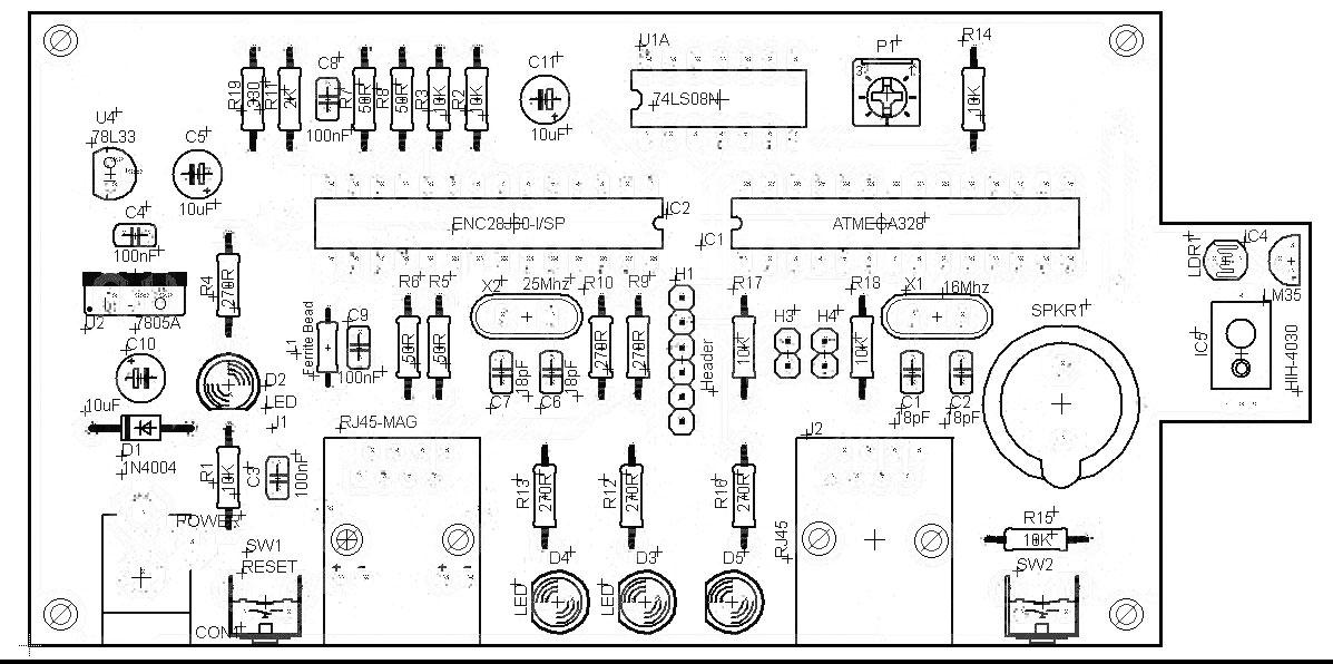
Board Component Placement
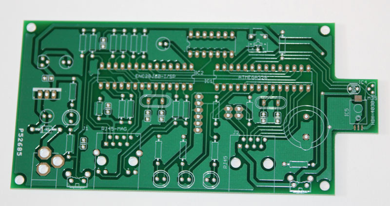
Here is a shot of the top Silk Screen. This was a prototype board we had made with Advanced Circuits http://www.4pcb.com/
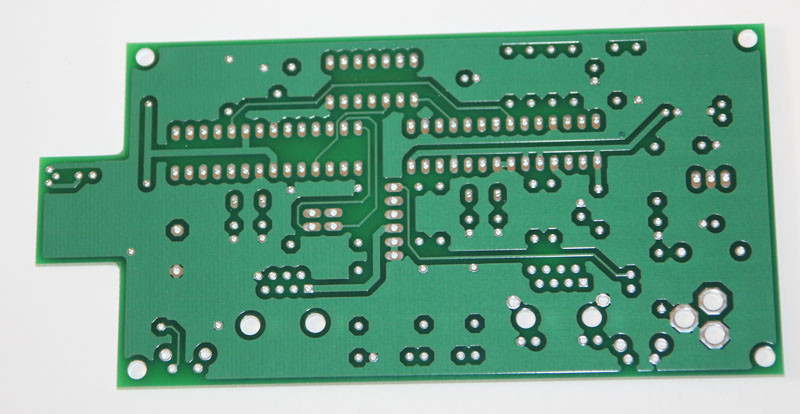
And the back of the same board.

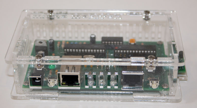
Here we have all the components mounted on the board.
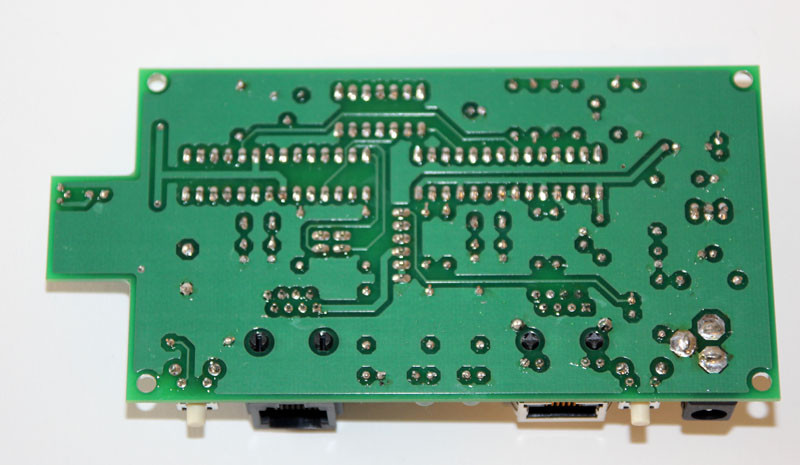
Solder joints for you all to see!

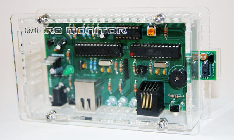
Laser cut chassis. Pattern is below. We use our own laser cutter but this will fit on the small sheet if you use Ponoko.
This is the finished chassis and board mounted. The top of the chassis is designed to be easily removed with the 4 screws in the corners so you can get easy access to the header. If your going to do a lot of tinkering, just cut a hole for your FTDI cable.
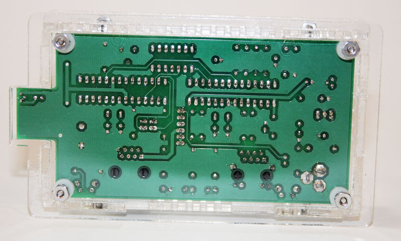
The back of the Chassis
And the Bottom. I left the breakout board RJ45 jack with a snap out cover in the chassis design just incase you don’t use it.
Downloads:
Chassis:
Circuit Board:
Code Example:
Related Posts
No Comment