This project has really taken a lot of time to finally get published. It has kind of taken a back burner to our other projects just due to its sheer scale. At the time of this article being written we have over 150 images and the article takes more pages than any other article we have ever produced. It’s just HUGE! So why is it getting finished now? Hardcore Gamer Magazine wanted to feature our older version of our dance pad. This new version is so far and above superior that I had to give them this. In fact they are featuring the world premiere of this article. So, with no further adieu. The ultimate dance Deck 2.0

Update: This artical was featured in the April 2007 Edition of Hard Core Gamer Magazine! WOOT!
This project has really taken a lot of time to finally get published. It has kind of taken a back burner to our other projects just due to its sheer scale. At the time of this article being written we have over 150 images and the article takes more pages than any other article we have ever produced. It’s just HUGE! So why is it getting finished now? Hardcore Gamer Magazine wanted to feature our older version of our dance pad. This new version is so far and above superior that I had to give them this. In fact they are featuring the world premiere of this article. So, with no further adieu. The ultimate dance Deck 2.0

The Dance Pad:
Sometimes the right method for invention is reinvention. Reinventing the wheel is not always the best course of action (unless you’re talking about government work or Software Development). When it came to the console interface we decided to do the easiest thing possible to accomplish our goal. A quick trip down to our local GameStop, some funny looks when we told them what we were doing with them and 40.00 for a set of their self branded dance pads and were off to a running start. These pads are for the Xbox. There are of course the PS2 verities as well and there is no difference in construction between the models. But the reason we chose the Xbox version was for the super easy ability to plug into a USB port on a PC. Just a simple converter is required and allows for pc play for free via step mania. Step mania is a free dance gaming suite and most dance games are based on its engine, both console and arcade. Just as a note there are Xbox to PS2 adapters for about 16.00 each. Giving the maximum flexibility possible out of the system
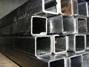
Steel:
With this project we decided to use 1″ square tubing for ease of construction. We also went to great efforts to create a design that would be both easy to construct as well as well as very durable. Using 14GA(.083) square tube we got from our local steel supplier and cutting it to length ourselves to save a buck or two. We strongly recommend using .083 or thicker material. Thinner materials may not have the strength to prevent warping and bending over time as well as being a little trickier to weld for the noob welder. The cut list for this project will be in the part list (yes, this is our first one…. but I think its finally appropriate on this project). Total cost for steel was somewhere around 95.00 and welding materials are about 10.00 per deck. Just a fair warning on costs, if you can’t cut and weld your materials yourself you can usually have the supplier of the material cut it to size for you at a cost usually twice the cost of the materials alone. These cuts are important to be accurate and I do not recommend using something like a hand hack saw for accuracy sakes. Additionally if you can’t weld the deck you can usually get it welded together for 100.00 or so. Everything other than the deck fabrication can be done in the comfort of your personal geek studio surrounded with your friends like Old Ben Kenobi and Mr. rubix.
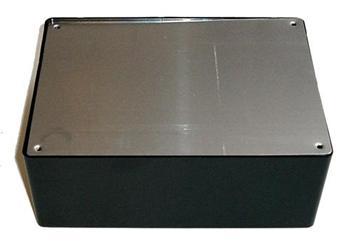
Project Box:
Our local Radio Shaq (yes I know this is misspelled) we found some simple project boxes. Basically a 4 ” X 8 ” plastic box with a screw on plastic or metal lid. This is where we’re going to hide the controller wiring from the dance pad to the deck. Cost was about 8.00
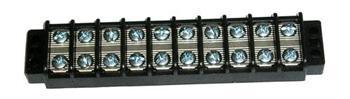
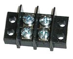
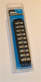
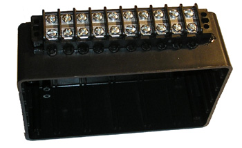
Large Terminating Block:
We used one of these terminating blocks to provide a modular interface between the dance controller and the deck in case of tile or sensor replacement. Basically a 10 screw terminal it provides the functionality we needed at a good price, somewhere around 9.00 each from our local home improvement store.
Small terminating Block:
We used one of these terminating blocks to provide a modular interface between the dance controller and the dance decks common ground. Basically a 2 screw terminal it provides the functionality we needed at a good price, somewhere around 3.00 each.
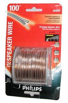
Wire:
We picked up a couple spools of this 24 gauge speaker wire at our local super store for about 9.00 each. We chose to use the clear plastic coated speaker wire in this version for all our lighting electrical systems.
The Deck Clamps:
In the prototype deck we chose to not use clamps due to the weight of the tiles. But this made so many dancers worry about sprained ankles that we decided to add them. But a run of the mill normal clamp would be lame (lame = not very innovative). So we designed a set of deck clamps that would allow you to adjust the step pressure required to trigger the sensor. Thus allowing for an adjustable intensity of work out beyond the step count method. 12.00 USD
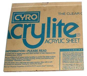
The Deck Surface:
Another change we made in this new version is going with 1″ thick tiles. The reason for this change is not safety or weight limit concerns. It would be 10X stronger if we went with 1/2 inch polycarbonate tiles instead of these 1″ thick acrylic tiles. The reason we went with the thicker tiles is in making the sensors more sensitive, and aesthetics. The lighting is so much more brilliant with 1 inch tiles that it really was the right choice for us.
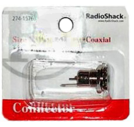
Power Connections:
One of the goals we wanted to achieve with this new deck was greater storability. A quick stop by our local radio Shack for some power connections and we have a modular power system. Additionally this helps with the scrounging points as you can scrounge up your power supply and make it work like it was designed originally for this. 5.00 usd
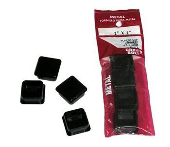
End Caps:
Our local home improvement store had these 1″ square tube end caps for about 2.00 each. Well 2.00 each would be a barging if it didn’t take 20 minutes and 3 drones to find them. These help reduce the risk of personal injury one could sustain from the top surface of the deck. Additionally they address the cosmetics by covering up the hole cleanly. One thing to watch for with these is on the install. Use a rubber mallet wrapped with a wash cloth or something similar to pound them into the tubes. As we are using a slightly heavier square tube the inner walls are narrower than what these are meant for. So they will need a little persuasion to seat all the way.
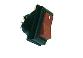
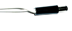
Power Switch:
The lighting system needed a switch so we could turn it on and off as we wanted. We chose this from our local electronics shop due to its ruggedness as well as it being oversized. This adds some convenience to just give it a tap with the toe and your off and running in place looking kind of silly.
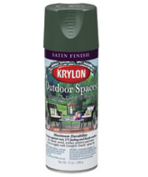
Assorted Sprays:
We used several assorted sprays in this project. Spray paint for the deck its self. Degreaser and rust removers and a window frosting spray for the details in the tiles. With the amount of spraying in this project if your not experienced with it… you will be by the end of it. We spent about 40.00 total on assorted sprays when it was all said and done.
The Lighting System Heart:
Once again we find another excellent example of a “don’t reinvent the wheel” opportunity. This has to be one of the coolest lighting systems for pc’s I have seen in a while. Basically providing 4 pods and each pod has a RGB LED in it. You can mix the color with the control panel to any color you want! And to top it off its super super bright. We got these at Newegg for about 20.00 each and 2 per deck so we can cross fade 2 different colors. And with 2 decks side by side you can go blend them to go from green to aqua to blue to purple. The last page has some pics of basic fading that they can do.
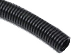
Conduit:
This flexible split conduit can be found at your local hardware store or auto part supplier. It’s cheap, flexible and easy to work with. You can cut it to length with some standard utility scissors and the tube can be reinforced with a little electrical tape.

Sensors:
This part about made me lose my mind. I came up with over 200 sensor designs. The goal being a balancing act of price, durability, and ease of construction. Ultimately we came up with a super simple design (yes I know the acronym K.I.S.S.) that is far superior to anything we had made previously. The new sensor consists of high density Teflon, stainless steel strips, and a little super glue and some wire. Total cost per sensor 1.80
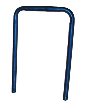
The Bar:
Danny is really into this whole DDR thing. So mid way through the project he added scope by wanting a bar. Luckily I knew just what to do. I sent him down to the local exhaust shop and they use their presses and materials to make some amazing bars for about 80.00 each. Considering the professional look to these when finished its was money well spent. But PVC would have worked just as well I suppose….
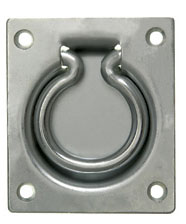
Handles:
When I started planning this new version out one of the requirements was for it to be easier to handle. So… I added handles. simply put these counter sunk flush pull ring style handles were perfect both space and style wise for the deck, this allowing for greater ease in moving them around. We use true value flush pull rings for 4.00 each.
One note on power tools: use them at your own risk. Be sure to read and understand any and all documentation on the tools you use. No amount of documentation can make up for experience, but there are many people with serious eye injuries from the school of hard knocks. If you don’t know what you are doing, don’t do it, and find someone that can help.
Cut List: (per deck)
All components are cut from 1″ square mild tubing with a wall thickness of .083 or thicker.
20 – 36 1/4″
8 – 6″
6 – 6″
This is roughly 67 continuous feet of material. Remember to purchase more material than you need as that is continuous length and the average lengths are 10 and 20 ft respectively. Also make sure you account for blade width. If you don’t you will be off by 1/8th of an inch and the tiles won’t fit with the clamps.
This should be self explanatory.
This is an exploded view focusing on the upper half. Once again… self explanatory.
This is a view focusing on the lower half. Once again… self explanatory.
| Part List: |
| Part | Details | Quantity | Cost | Total |
| Steel | 1″ X 1″ X 14GA(.083) | 1 | $95.00 | $95.00 |
| Dance Pads | Game Stop Version | 1 | $19.00 | $19.00 |
| Project Box | 4 X 6 project box | 1 | $5.00 | $5.00 |
| 10 terminal block | 10 Terminal Terminating Block | 1 | $6.00 | $6.00 |
| 2 terminal block | 2 Terminal Terminating Block | 1 | $2.00 | $2.00 |
| 24 Ga speaker wire | 100 Ft Spool of 24 Ga speaker wire | 1 | $4.00 | $4.00 |
| Wire | 16 Ga Mono Wire 10 ft | 1 | $3.00 | $3.00 |
| bolt | 8″ long 1/4th Dia Bolt | 4 | $0.70 | $2.80 |
| Washers | 1″ Washer with 1/4th Inner Diameter | 8 | $0.05 | $0.40 |
| Spring | Heavy spring with Id of 1/4th | 4 | $1.00 | $4.00 |
| Nuts | 1/4th Hex Nut | 4 | $0.06 | $0.24 |
| Wing Nut | 1/4th Wing Nut | 4 | $0.06 | $0.24 |
| Acrylic | 1′ X 1′ @ 1″ Acrylic Tiles | 12 | $15.00 | $180.00 |
| Acrylic | 3″ X 36″ X 1/4th” | 1 | $4.00 | $4.00 |
| Power Jack | Male Power Connector | 1 | $2.00 | $2.00 |
| power jack | Female Power Connector | 1 | $2.00 | $2.00 |
| Power Supply | 12V 1000ma Power supply | 1 | $7.00 | $7.00 |
| Eng Caps | 1″ Square End Caps ( 4 per package) | 1 | $2.00 | $2.00 |
| Power Switch | Oversized Rocker Switch | 1 | $2.00 | $2.00 |
| Push Buttons | Oversized Momentary Switch | 2 | $2.00 | $4.00 |
| Spray Paint | Silver Paint Rustolium | 3 | $3.00 | $9.00 |
| Spray Paint | Blue Sparkly Rustolium | 1 | $3.00 | $3.00 |
| Spray Paint | Clear Rustolium | 4 | $2.00 | $8.00 |
| Cotter Keys | 2″ Long Cotter key | 2 | $1.50 | $3.00 |
| LED Kit | Chameleon PC LED Kit | 2 | $10.00 | $20.00 |
| Conduit | 150″ of 1″ flexible split conduit | 1 | $10.00 | $10.00 |
| Teflon Strips | .022 – .050 Raw Teflon Strips | 18 | $0.30 | $5.40 |
| Stainless Steel | 3/4 X 11″ X .022 Stainless Strips | 18 | $1.20 | $21.60 |
| Bars | Custom Bent Bars | 1 | $80.00 | $80.00 |
| Bar Supports | Custom Flared Bar Supports | 2 | $5.00 | $10.00 |
| Flush Pull Rings | Basic Flush Pull Rings | 2 | $3.00 | $6.00 |
| Hot Glue | One package of 20 | 1 | $2.00 | $2.00 |
| Self Tapping Screws | One Box of 1″ self tapping screws | 1 | $5.00 | $5.00 |
| Castors | Solid Metal Castors 2″ | 2 | $5.00 | $10.00 |
| Super Glue | one bottle thick set cyanoacrylate | 1 | $4.00 | $4.00 |
| Solder | one small spool | 1 | $2.00 | $2.00 |
| Electrical Tape | Basic Electrical tape | 1 | $1.00 | $1.00 |
| Aluminum L Stock | Aluminum L Stock 1/2″ X 1/2″ 36″ | 4 | $4.00 | $16.00 |
| Aluminum Plate Stock | Aluminum Bar Stock 1″ X 12″ X 1/8th” | 1 | $2.00 | $2.00 |
| Cable Fasteners | One box of 20 1″ screw down cable fasteners | 1 | $4.00 | $4.00 |
| Total – $566.68 |
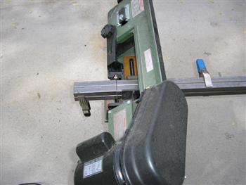
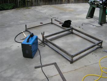
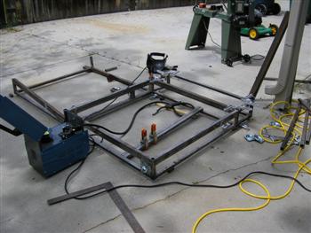
So back to the workshop… also known as the driveway. We needed to cut a lot of metal as precisely as possible. Luckily I had a light duty metal cutting band saw. These are very affordable from harbor freight or even eBay. Money well spent as you can make 4 cuts at once totally unattended and they will all be the same size for sure.
So starting the layout. The most important step is to get everything 100% square. We laid everything out before hand to insure the dimensions were going to be what we expected. Note the nice new blue harbor freight welder on the left. When you buy cheap tools expect results to match what you invested in them. This light duty mig caught fire mid project. I’m not a fan of the 100% duty cycle. Lucky for me that we lost it so I had the excuse to pick up a nice Lincoln mig.
A little trick we found was to pick up these aluminum squaring clamps at our local home center. They allow for perfect alignment and while we double checked for square on every weld we never had to adjust it once with these. It’s about a million times easier than using the little corner magnets and far more accurate.
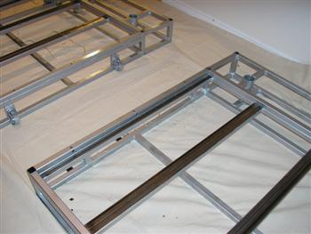
So here we go. Assembly was really a breeze. Another note on tools, the L Square you see in the lower center of the screen was my grandpa’s. The reason for pointing that out is that good tools are a great legacy for any geek to inherit or pass on.
More progress. We have the main structure done for one side and the second almost done. One trick I used was to use the 3 point tack weld method on the decks as they were welded up. This insures nothing will come out of square as you work.
Next up the rear bar support section. It is important to frame this totally in. this is about where the welder caught fire. I think Danny was conveniently at the hardware store during this meltdown.
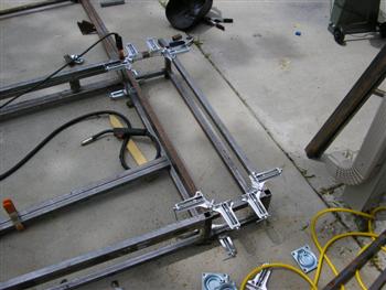
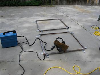
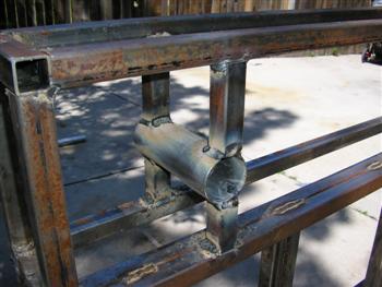
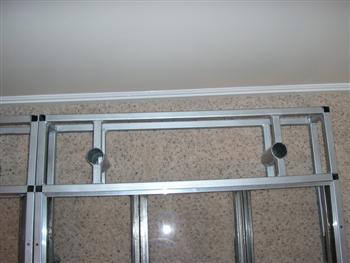
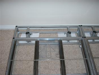
Here is a nice detail shot of the rear bar supports coming together with the clamps. By the way, did I mention that the clamps are really great and you should consider using them?
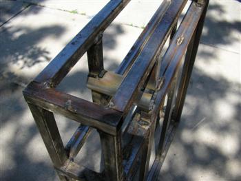
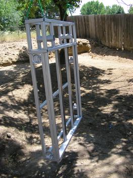
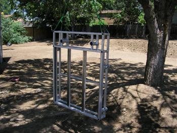
So here is the finished deck section. You will notice the deck has the full bar supports running from back to the mid sections. We will cut them later for bar placement.
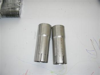
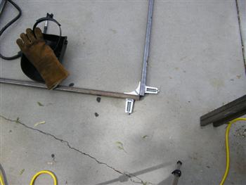
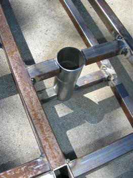
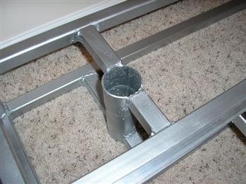
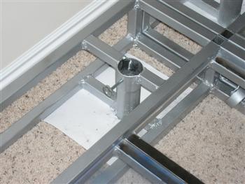
So when we went to a local exhaust place had them use some heavy gauge pipe and flair some ends for the bar receiver. The flare ensures a tight fit. We will notch the bottom of them out so they slot fit onto the supports. This gives us both an excuse to use our dremel on this project, but also more weld contact insuring greater strength.
Now we had the bar receiver parts we were able to cut the pipe to match it. we turned it upside down and traced the arch of the tube onto the bar supports and with a jig saw and a steel cutting blade we cut them so we would have a cradling tight fit.
Here is the bar support in place for a dry fitting. We had cut this a little wide on one side so there was a gap. This can be fixed with a little fill welding and some grinding to clean it up.
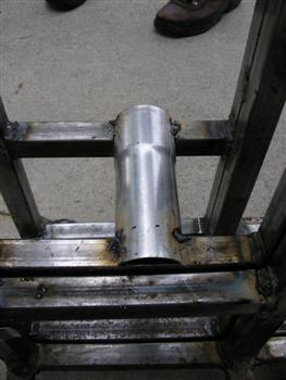
Next we tacked the bar supports in place and installed the bar to test and verify square. If you need to make any adjustments in angle of the bar it’s easier to slide the bottom forward and back than to cut it up top.
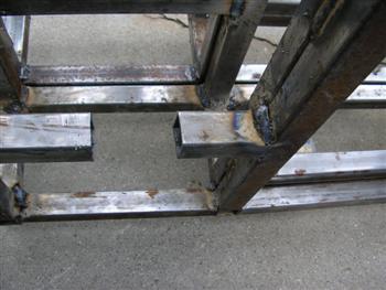
With the bar verified to be square we permanently welded the supports in place. It’s really important not to blow through the top half of the bars support when welding. If you do you will need to spend some quality time with the dremel tool grinding it flat. Another thing to watch for is splatter. We used a spool of flux mig wire and ran gasless. Now this is good for getting a little hotter and deeper weld. But it creates a lot of splatter. This splatter fuses with the walls on the inside of the tube and will have to be ground out. That part kinda sucked…
Just another shot where you can see the notched end of the bar support seated around the lower bar support with final welds finished.
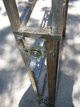
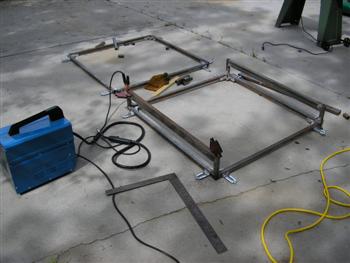
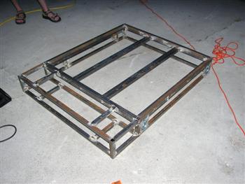
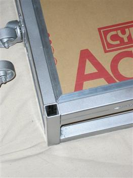
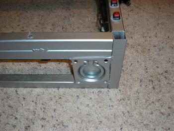
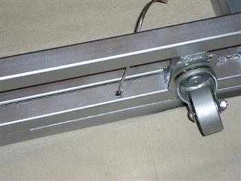
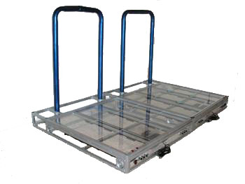
With the bar support installed we moved on to the wheels. That’s right I said wheels. We will be installing wheels on these baddies so that when the decks are turned sideways we can just clamp them together and they stand upright with the stability of 4 wheels so there easy to move or store. The wheels are staggered so that they will fit in the bar space of the other deck as well. That way you won’t have anything hanging out to step on or stub a toe on.
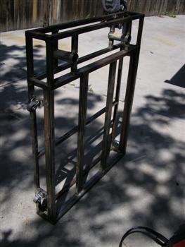
The deck with all its raw fab done! We installed the handles on the other side making it easy to pick them up and roll them around even at this point. One thing to remember when you’re installing the handles. when you start flipping and rolling this around make sure your still orienting the handles so they will close on their own when the deck is on the ground like normal. Its always a good practice to tack weld something. Step away from it. Then final weld it.
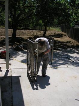
Now, as Danny was the one taking these homes, mixed with the fact he can’t weld… well I let him do all the grinding. Grinding is not fun. Make clean welds. And use a nice wire buffing wheel to remove rust from your materials if you need to.
The next step is to give this a coat of paint. We chose a nice silver rustolium for the paint on this project. Now spray painting is not hard. But it can be time consuming. So on this project we did 2 things. We used the little spray can handles you can attach to the spray can and make it into a little triggered gun. And we applied several coats of paint to the top surface of the deck along with several coats of clear so that it would have a strong durable finish.
Another tip is to let that paint fully cure. On a hot august day it takes a few hours to cure to a point you can be fairly rough with it. But it often takes 24 hours to fully cure.
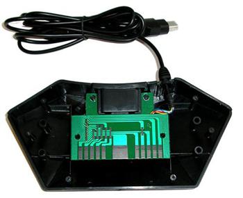
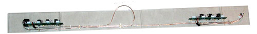
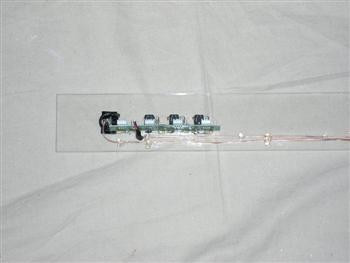
So here is the control box unscrewed from the dance pads we picked up. These are not overly complex by any means. But we will need to modify the board slightly for our needs. Step one is to remove the board from the plastic. This can be done with just a little pressure. There are no screws. Just melted plastic holding it on.
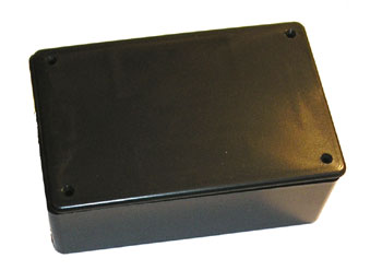
Here is the project box we will use. We chose to go with the plastic lid so it looked a little cleaner. But you can choose either one.
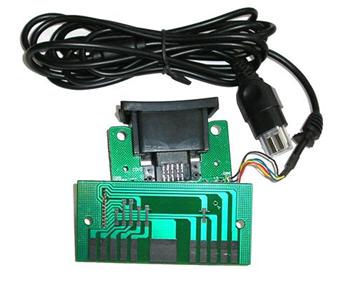
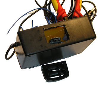
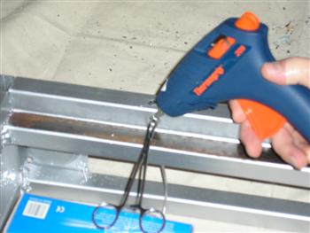
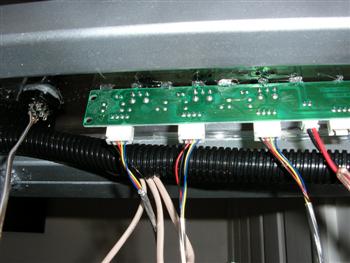
Here are the innards of the dance pads control box. Before you do anything to this at all I would recommend taking a healthy blob of hot glue and applying it to where the small wires attach to the board. This will insure you don’t snag something and rip them out of the board accidently.
Here is a diagram of the control board’s outputs. If you connect any of the main terminals to the common ground it will activate that function. Hence it being a common ground. A ground that is common to them all. A single point of grounding they all share commonly. One ground to rule them all, one ground to find them. Etc… (If you haven’t noticed I kinda beat the common ground thing to death. I received so many emails about common grounds that maybe I have some pent up animosity towards them now.)
Step one is to take the 10 slot bar and mount it to the plastic box. The method is easy but it needs to be secure. Start with applying a liberal amount of super glue to the project box and bond the bar to it. To help hold it in place put a few small drops of hot glue on each corner to just be piled off later. When the glue is dry use a small drill bit or a hot soldering iron to melt holes through the box from the mounting holes on the bar and use screws to attach them permanently.
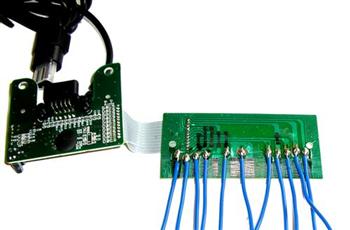
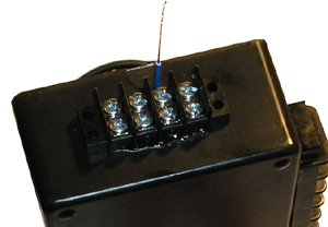
Next using some sandpaper or a dremel tool, buff off the black coating on the terminal portion of the controller card. One thing to think about here is safety. Do this outside! Buffing this off will also buff off some of the lead etchings and make it airborne. When you’re down to bare metal solder on wire leads to the terminals leaving plenty of slack.
Using a razor blade cut a hole for the memory card reader housing and slide it into the project box. It’s important to make sure this is a tight fit.
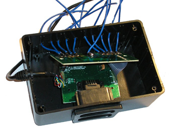
Drill small holes large enough for the wires to pass through. Feed all the wires out the side of the project box to be attached to the terminal bar later. Secure the memory card reader housing and board to the project box with hot glue and super glue for the permanent bond.
With all the wires fed through use hot glue to cover where they meet the circuit board to help reinforce them against the shock of a 270 lb guy dancing 1 inch above them. Also apply a little glue to the inside of each hole so the wires have some shock protection.

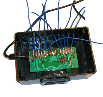
Next cut all the leads to size and strip them. Using a hot iron and some solder tin them (saturate with solder) so that there all nice and shiny silver.
Using some pliers bend the wire leads around the terminal posts on one side and secure the screw very tightly. I never worried about breaking the block by over tighteng them. Now at this point you will see the common ground we left dangling. We will mount that to the side in a second. But we wanted at this point to test that the box was working. To do this plug it in as you normally would and touch the ground to each post and note its functionality. XBCD and a USB adapter is the easiest way to test the dance pad all around.
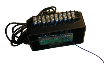
Using the same methods as previously stated mount the side master ground terminal block to the project box.
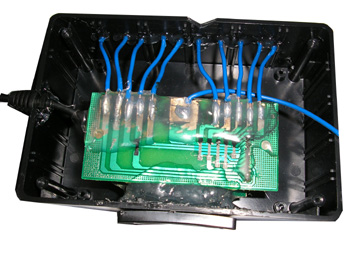
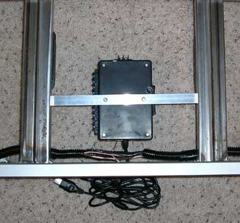
So here are the innards of the deck interface completed. Note on the left the notch we cut in the project box so the little stress absorber would slot into the box nice and neatly.
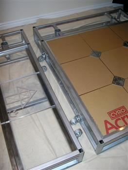
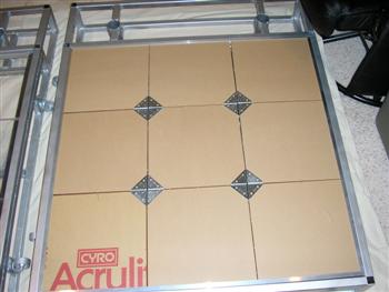
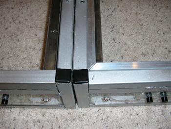
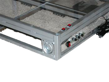
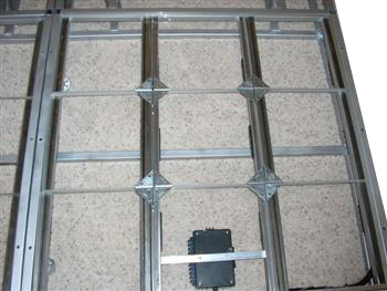
Before we start into the assembly process of this project. We need to dry fit the components together. You can see clearly here the interlocking wheels as well as an aluminum frame around the deck on the right.
So for the assembly process our first step is to drill the access holes for the LED’s. Using a good metal drilling bit drill all the way through the deck. If you don’t like the holes on the top of the deck you can do one of 2 things to address them. Don’t drill through the top of the deck. We did that with deck 1.0 and the wire fishing wasn’t fun. Or fill the holes with hot glue or get some covers for them in the hardware department of your home improvement center. If you fill it with hot glue the light will emanate from the holes and it looks kinda cool as reference marks.
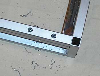
Using a couple pop rivets or even some self taping screws if you wanted to, mount the lid of the project box to a piece of aluminum bar from your local hardware store. Center it between the deck rails and rivet or screw it permanently to the deck. Once secure screw the lid back on the rest of the project box.
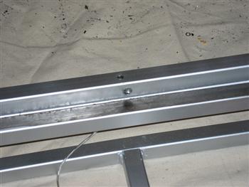
One of the most important steps both cosmetically and functionallyl is to strip and buff off the tops of the supporting rails. Paint overspray, rust, grease, blood….. Well it will all interfere with the sensors as well as look horrible with the clear plexi, and the shiny metal is just cooler looking than oxidized bare metal. One thing I heard over and over is “he says to buff it but doesn’t do anything to prevent it from rusting again.” my response to that is… in a clean dry environment like your house, this should not likely rust again, and if you need to spot clean it just get a scotch bright pad. meh….
To hold the tiles in the deck we used some aluminum L stock with 1/2 inch sides. We mitered the corners at 45 degrees for a snug fit then took them to someone that had a tig welder to weld the seams. After the frame was welded we installed it inside the frame with some flush mounting pop rivets. This will hold every tile in the deck securely. And it makes the center tile the master tile for both tension as well as removal of the tiles.
Here is a shot with the deck clamps top portions installed. The deck clamps have not been assembled at this point. We are just checking for spacing and insuring they are fitting well.
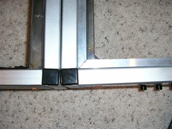
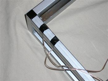
Here is a shot of the caps installed. These really are important for safety. If we didn’t install these and Danny was to find them the hard way we would have to start calling stumpy…. and that doesn’t work out well for anyone. Especially his dating life.
So here is the part that sucked. I realized the welding splatter was inside the pipe. So I got out the dremel tool and went to work. I used 16 sanding drums cleaning all that splatter out. It realy realy realy sucked. a lot!
The back section of the deck with the bar supports all cleaned out.
Here is a shot of the cleaned and painted handle.
The 2 decks joined. We installed simple clamps we picked up at the hardware store to keep them locked together.
This is the bar support with a hole drilled in it for the cotter key that will hold the bar securely in place. The cotter key is very tight in the hole but fits.
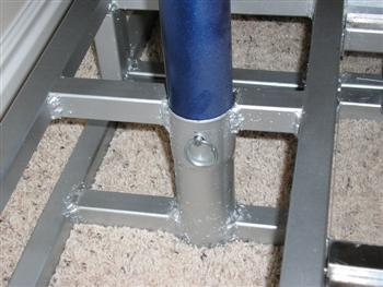
We chose to paint the bar a sparkly blue and give it several coats of clear to make it really pop. The pictures really don’t do it justice. With the bar installed snugly drill through the hole in the receiver so that the holes will line up for sure. Install the cotter key and make sure it’s tight.
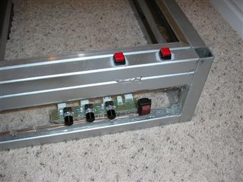
Next up drill holes large enough for some heavy duty momentary push buttons to fit into the deck.
With nice long leads soldered to the buttons insert them into the holes you drilled and fish the wires out the other end. Using some extra strength super glue applied liberally; affix the buttons to each deck. One tip I found was to use electrical tape stretched a little tight to insure the buttons don’t twist or move as the glue sets. If you want more reinforcement use hot glue or rubber grommets on the exit holes.
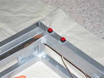
So here is the buttons dried and set. You will notice a slight white haze around the buttons on the paint of the deck. This is created by the vapors from the glue as it cures and can easily be polished off with a rag.
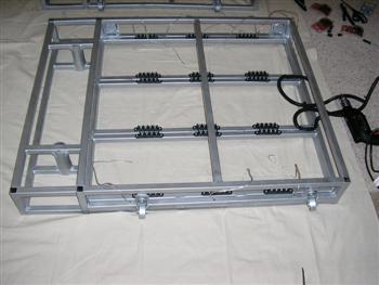
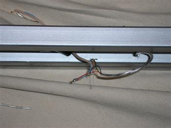
So on to the main wiring. Using some self tapping screws attach the large terminating blocks to the deck so they will be positioned in the center of each tile. We found these online as surplus for 1.00 each. They were a little large, but I think they added more aesthetically than our other 2 terminal blocks would have.
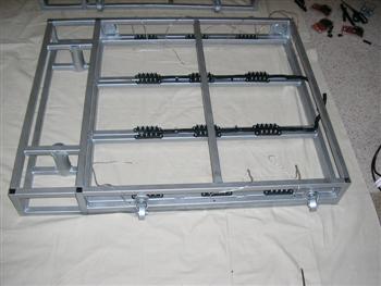
Next run the conduit up the lengths of each of the 4 supporting arms just to the side of the terminating blocks. In the center it should have room to fit between the blocks cleanly. Leave the seam in the conduit facing up.
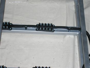
Using some 1″ screw down cable ties and some self taping screws attach the conduit to the deck Permanently.
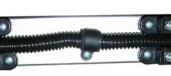
Here is a close up of the cable tie downs. One thing we chose to do as we had a ton of extra adhesive foam sheets was to cut small pieces and rap the conduit where the cable ties clamped on them. This acts as a sound dampening and vibration dampening material so we get a little longer life out of the deck.
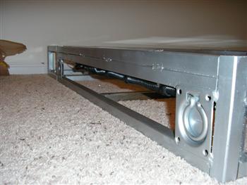
This is what the deck looks like from the side with the conduit installed. I really like the heavy industrial look to it.
On to the lighting install. With the plastic casing removed from the RGB LEDs and the wires cut to a nice length. Fish the wire through the deck leaving the LED and a small amount of the leads dangling out the hole.
Just another shot here clarifying the wire path for the LEDs wiring.
Using some locking forceps clamp carefully onto the led and guide it into the hole we drilled. Using some hot glue injected in the front and top of the hole to secure the led in place. Make sure the glue is nice and cool before moving on.
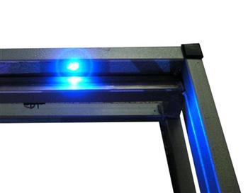
Here is the finished product from the LED install. If you have a little oozing of extra glue you can trim it off with a razor. This end result should be totally flush with the bar.
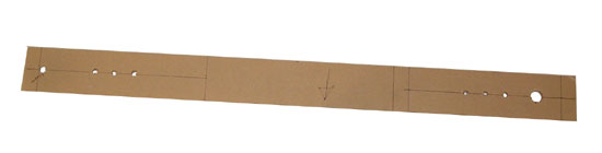
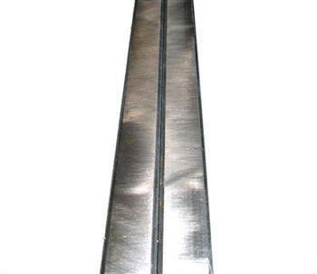
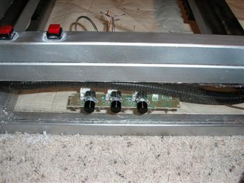
With the base wiring for the LED’s and buttons done we need to start into the control panel on the front of the dance deck. We chose to go with a very symmetrical layout for our decks. This is a 3″ X 36″ sheet of acrylic that is 1/4 inch thick. We used standard drill bits at very high speed to slowly drill the holes in the material using more of a melting technique
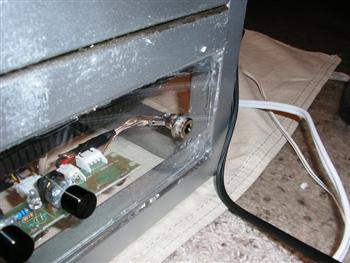
Assembly is really easy. Using the nuts that hold the controllers to the original face plates we will mount the controllers to our new control panel. Installing the power switch and power jack go exactly the same way. Just insert and thread on the nuts. Then using some 16 gauge speaker wire and some small drops of clear hot glue to hold it in place we connected the electrical. This is really easy just “Y” out the power from the power connector and run a lead from the positive terminal to the power switch.
Here is a little closer look at the wiring on the power switch side of things.
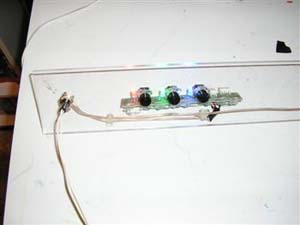
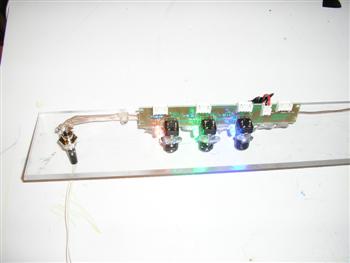
With the panel assembly finished we need to test it out. Plug in the power and hit the power switch. If the LED’s light up on the panels your in great shape.
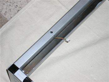
One last shot for verboseness sake. Here is the back of the power panel with the power lead connected. Use a little hot glue to insulate bare wire connections as needed.
One more tip that we learned. We scrounged up some 12V 1000MA power supplies for this projects lighting system. These didn’t match the sockets we bought nor were the same between the two of them. We decided to cut off the existing plugs and install new ones. This was a rather painless project.
The next step is to install the front acrylic panel. To do this I chose to use some clear hot glue for ease of install and getting it done quickly. Alternately you could use a clear silicone if you wanted to wait for it to dry.
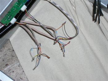
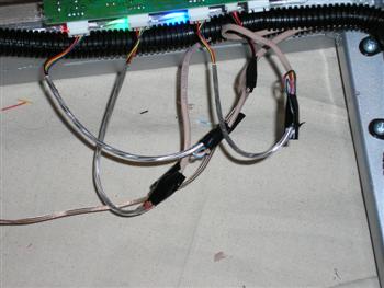
With the LEDs and front panel installed now we need to splice into them and extend them to the front console. This is really simple just time consuming. Using some wire strippers strip our leads. Then run some 4 wire phone wire (solid core) to each led through the conduit. Strip the ends of those wires and match color to color in a way you will remember and repeat for all the connections. Using a soldering iron use a small drop of solder on each connection to insure it will be strong and prevent shorting.
On the controller end of things we basically repeat what we did the LEDs matching colors and snapping the connector ends into the lighting controller.
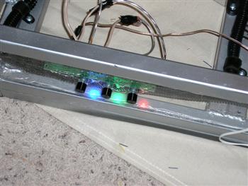
Before we close up the wiring we need to test our connections. To do this we will just be powering up the chameleon mixer and cycling through each color. If you end up with a dead LED or color in a led check your wiring first of all. And if you have to replace a LED just drill out the holes and glue and install a new one.
With our wiring verified we will proceed to clean up the wiring. Starting with using some electrical tape wrap each connection to guard against shorts.
Just another shot of the installed panel with the lights on.
Here is a close up of the power plug and controls from the front of the deck.
The next step is to start hiding the cables I the conduit. This is fairly flexible stuff and easily stretches to hide a lot of cable. One tip is not to leave long leads so you don’t have so much to stuff in the conduit.
So there is the finished panel. We drilled one large hole in the center of it for the wires from the controller box to pass through.
With the 2 decks pressed together I wanted to point out the power connectors. Having them close is really nice for cable management. But one trick we learned after the fact was to build a custom “Y” cable and use only one power supply to power both decks.
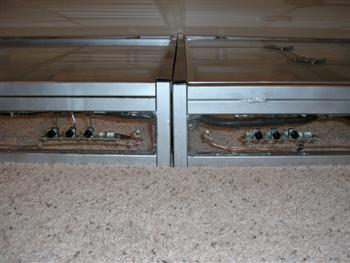
Here is a close up of the right side of the right deck
Here is a close up of the left side of the right deck.
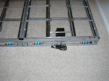
Here is a shot of the 2 decks side by side and the panels installed.
Ok this is the last shot of the assembled deck for now… I think that that our verboseness of pics quota was met. Don’t email me saying you want more. Do you realize how hard it is to come up with clever crap to say on every picture?
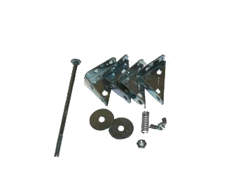
The parts for the deck clamps are simple. One 5-6″ long 1/4th” bolt. 2 washers, one wing nut, one standard nut, one spring that will fit the bolt and 4 steel corner brackets.
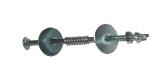
This is the basic assembly of the spring tensioner. This allows the decks tension on the sensors to be adjusted. By tightening the nut. the wing nut binds the bolt so it won’t come undone as the deck is used.
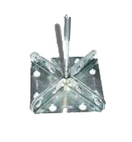
With the head cut off the bolt we will be welding the fixture together as you see here. If you get sloppy with your welds you will need to grind the inner surfaces clean or you will have problems with the tiles response.
Here is a quick diagram of the way this works. The clamp holds the tiles securely in place. The spring provides the tension source so the sensors can be adjusted in sensitivity.
Here is the final product. The finished deck clamps installed in the deck. If you wanted to you could get some thin acrylic and make a decretive cap for each one… but I really like the industrial look of these.
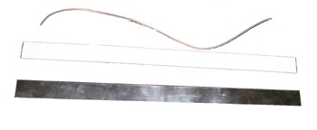
The sensor assembly is really easy. We are using some K&S Engineering stainless steel strips that are 3/4″ wide and 12″ long (cut to 11″ in length) and two types of raw Teflon strips are 1/4 inch wide and 1″ and 1/4th inch long. some super glue and some speaker wire piled into separate wires.
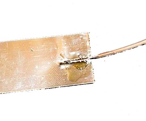
Before you apply the Teflon and glue you will need to install the wire. as we don’t want to add thickness to this if possible we will be removing a little notch of material from the metal strip that the wire can sit in. then we will solder it in place so its flat. Using a little sand paper just knock down any bumps you may have from the solder.
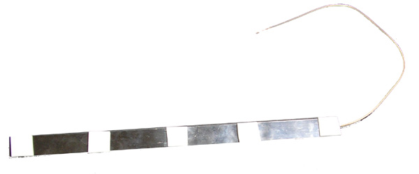
Here is the finished sensor strip. You will want to install this narrow strip side up when you install it. This will more or less just float between the deck and the tiles. If you have low tension between the tile and the deck in the clamps you may want to apply a small amount of double sided tape to the tile facing side.
Here is a quick side profile of the sensor. Material thicknesses have been exaggerated for clarity of diagram. It is worth noting that this is exactly the same principle that commercial decks use.
Summary:
I realize this was a both a long project write-up as well as highly anticipated by many. I’m glad we finally got it published. We really don’t have many articles just sitting there waiting to be written up. But this project was daunting for me for some reason…
Danny sure loves these dance decks though. I think we so far exceed every expectation of his and its made him a bit of a geek icon in the local Dance Gaming Groups.
This is not meant to be the stand alone definitive guide. The first dance deck has a lot of important things we chose to gloss over. If you choose to build one of these baddies yourself I recommend reading both articles..
Update: This artical was featured in the April 2007 Edition of Hard Core Gamer Magazine! WOOT!
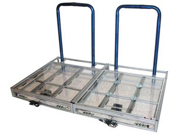
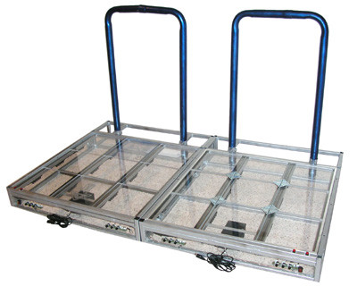
So here are the finished decks side by side.
Another shot of the dance decks.
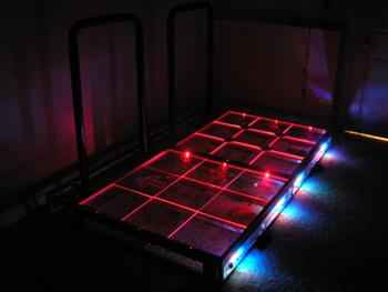
Now we play with the lighting. The Red these LEDs put out is amazingly vivid.
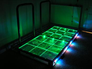
The dance decks in blazing green.
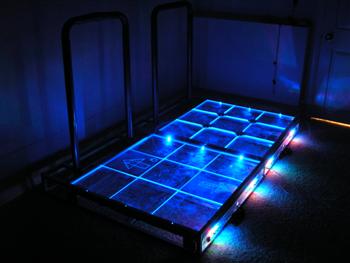
A nice solid blue. The blue the LED’s put out is very bright. The only down side is it’s easy to overpower some colors when mixing them
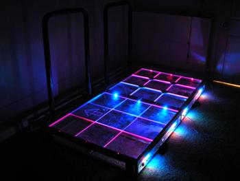
A nice red to blue cross blend. Note the blues penetration on the left deck.
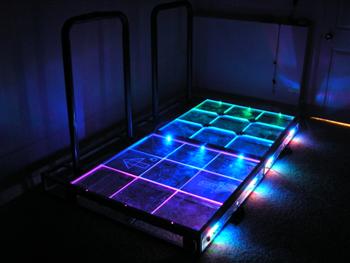
Here were blending 3 colors to make the decks lighting more interesting.


Hello! I’m trying to build this but have a few questions is there anyway you can email me to ask some questions?
Europe, and in Ancient Russia