
Overview:
Today I realized that we haven’t published many articles this year on invent geek because the articles and projects we are working on are larger in scale and require a lot more time and resources that our typical past articles. However I wanted to publish a simple article detailing one of our boards we have put together as an accessory module to one of our larger systems that will be published soon.
This simple, low cost sensor module is designed to provide any Microcontroller platform data on temperature, humidity or both in a low cost and highly reliable package. to accomplish this we chose to use sensors from Honeywell and National Semiconductor due to their relative low cost and ease of use. this module is designed to operate from a 3-5V DC with 2 simple analog read pins for the respective sensors data.
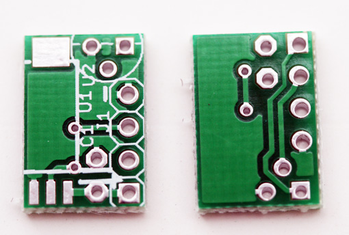
Circuit Board:
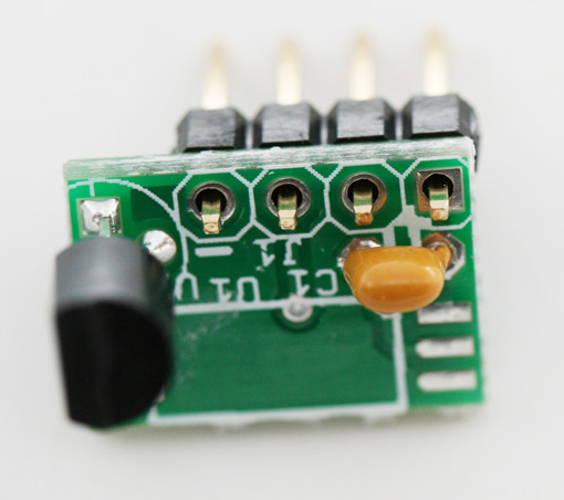
Here we have our tiny little sensor board. This board measures 0.370 x 0.550 and takes about 10 min to solder all the components to it. – Visit Summary or Overview of this project to purchase this board or kits.
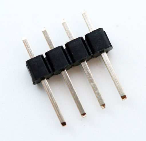
4 Pin Board to Board Connector:
Here we have a simple 4 pin header for this board. This is totally optional of course depending on how you intend on using it, but it’s great for breadboard experimenters.
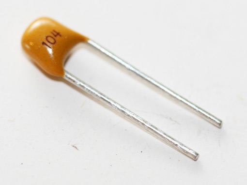
0.1UF Ceramic Capacitor:
The board also includes this cap as a noise filter.
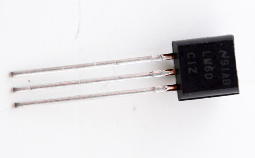
LM60 Temperature Sensor:
Both the temperature and humidity sensors are optional, however the LM60CIZ is very low cost and easy to use. You can substitute a LM61BIZ if you needed to.
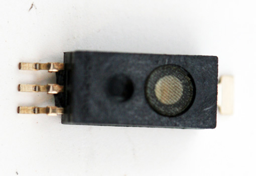
HIH-5031 Humidity Sensor:
The Honeywell HIH-5030 and HIH-5031 can interchangeably be used for the humidity sensor on this board. I really like the reliability and ease of use of this little sensor.
So we will go through a simple step by step assembly of this project for those who are interested in the order of its construction. if this is a total snoozer for you just skip over to the project overview.
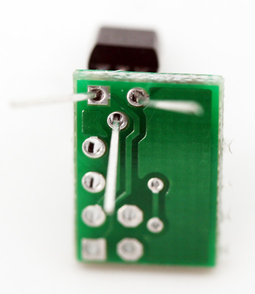
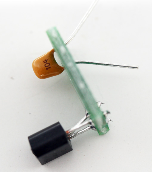
For those interested in its construction, congratulations this is step one! Insert the LM60 temperature sensor as seen in the picture above.
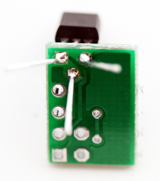
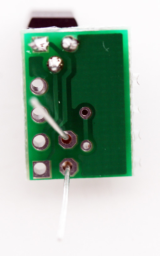
Next solder the leads to the board, I found that a left to right approach worked best for me.
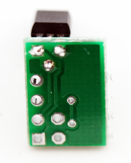
Yep… next we will cut the excess leads off.
Next we will install the capacitor. There is no polarity on this component to worry about.
Another view of the capacitor installation for visual clarity
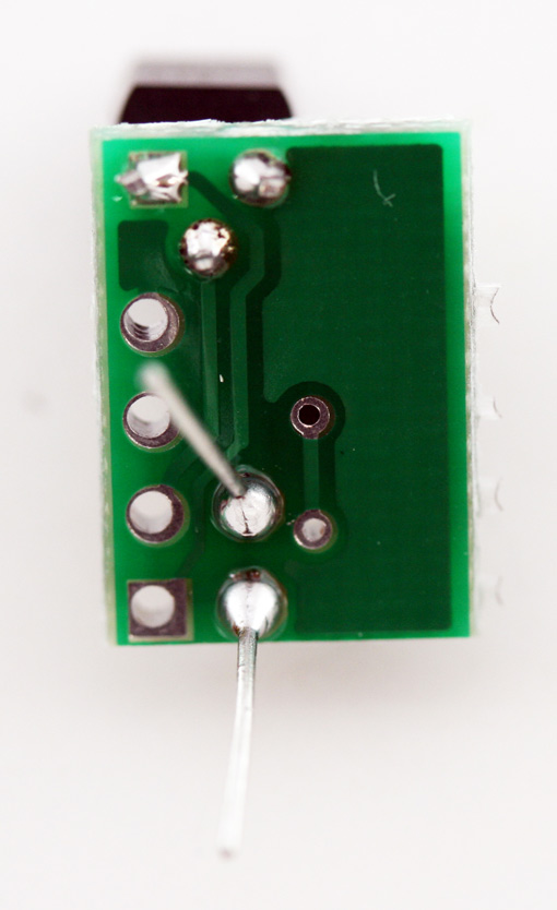
Here we see the soldered leads. Trim the excess lead from the capacitor.
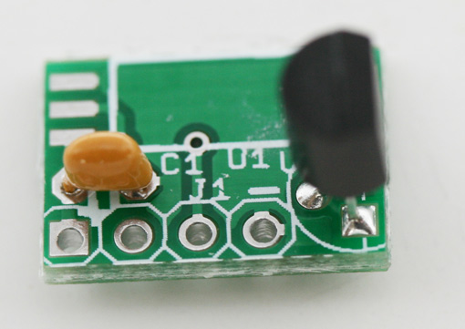
Here we can see the components oriented on the board.
Now we will install our 4 pin header. If you have a bread board you can use to help in the soldering process I recommend using it. Insert the header into the board and then solder the leads.
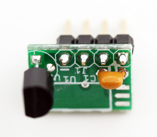
Here we have the soldered leads. yay! no trimming necessary.
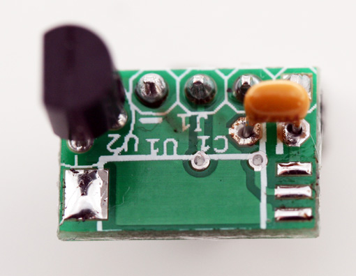
Now… this is a trick I learned from a friend of mine. Using your soldering iron very slightly apply some solder to the contacts for the surface mount humidity sensors pads. it should look like this when you’re done. if you join the smaller contacts, clean your iron tip of excess solder and then go over it again and it will likely clean up the bridges. place the component on the board and starting with the top joint heat the solder and tabs to fuse and connect the component.
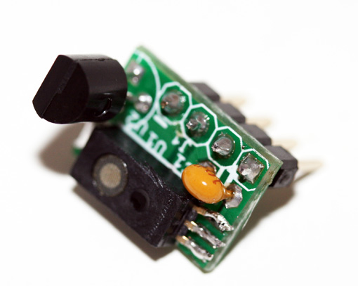
Here we have the finished module! Kind of neat isn’t it!
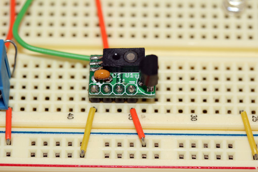
Now to test it. Here we have mounted it to our breadboard and we have connected it to pins 2 and 3 on our Arduino as well as connecting the 5V and GND to the bread boards power rails. We will post some code soon as an example for the arduino.
So if this looks like a project you would like to try you can get a board, or kit below by donating to our site. All donations will be reinvested into more future projects and publicly available kits and to pay for shipping of the kit to you.

Hey, thanks for the insight !
However, the datasheet of the HIH-5031 specifies “minimum load 65 Kohm. I can see that you are not using resistor. Can you detail why you don’t need any resistor please ? That would be much appreciated !