Laser Arduino Instrument

Overview:
So this project has been lying around for a while and I finally found some time to write it up. I was inspired with several of the other popular microcontroller based laser instruments that have been floating around on the web over the last year. Ultimately I wanted to put together a project that was more compact and portable and this is the end result of my first attempt. While I had a lot of fun building this project I honestly learned more about how I would make it different in the future. There are many different ways to design the interface a musician would use and by far its more interesting to design new and experimental ways to expand this concept.
Arduino source for this project can be downloaded here.
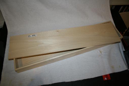
Wood:
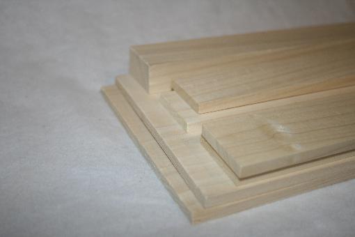
For this project we picked up some precut .250 poplar. We used all precut stock that is the same length to make it simple to construct and reduce the number of cuts we needed for this project.
Cut list:
2 – 24 X 5.5 X .25
3 – 24 X 1.5 X .25
1 – 24 X 1.5 X .75
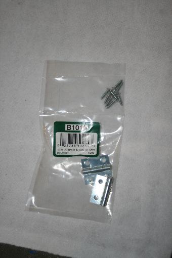
Hinges:
To allow access to the internals to change batteries we will be using a simple hinge kit from our local home improvement store. These are chrome and I ended swapping them out with brass for constancy of the metal parts in this build.

Wood Glue:
Wood glue will be all that holds the project shell together. Its strong, cheap and easy to work with.
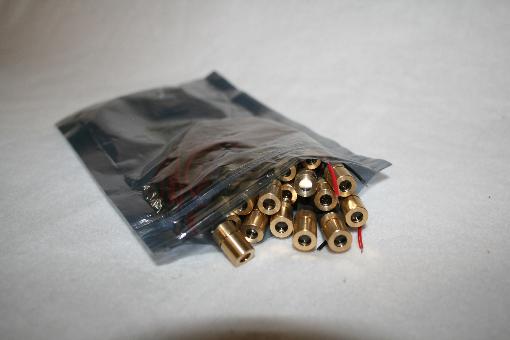
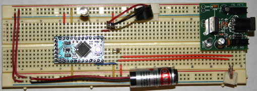
Freaking Lasers! :
So a while back I did an art project for a local studio that used a bunch of cheap red lasers. These are about 1.20 each and are the typical laser found in cheap laser pointers. They have a brass housing for the laser diode and a focusing lens.
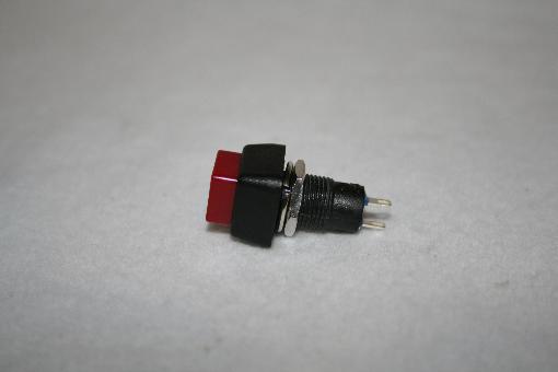
Push Button:
Push on off button for powering the system on and off. No frills here, just don’t buy them at the highly overpriced national chain if you can avoid it.
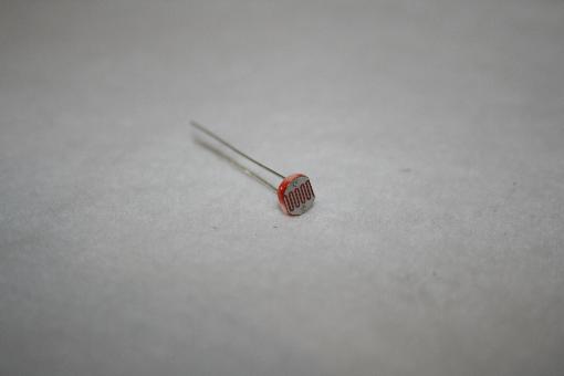
CdS Light Sensor:
For this project we will be using 9 light sensing CdS. These simple and easy to use sensors are tremendously useful in a good deal of projects. I recommend buying these from digikey as they are a fraction of the national chains pricing.
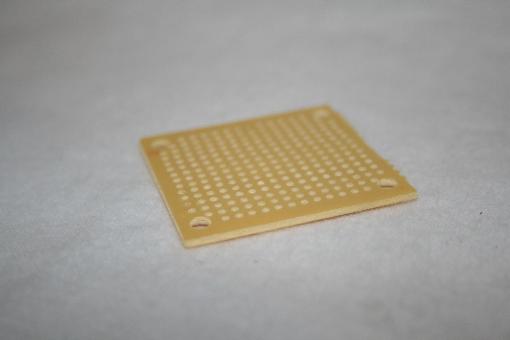
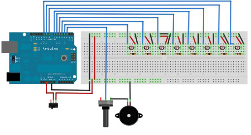
ProtoBoard:
For our pinout for the interface on our arduino we used a simple protoboard so we could use a wave shield for future experimentation. The case has enough height to support a shield on the arduino so we may as well use the space wisely.
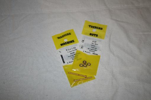
Brass Hardware:
We picked up some brass hardware to hold the top wood bars to the base box. 4 screws at 1.25” will cost you about 5.00 but cosmetically its worth it.
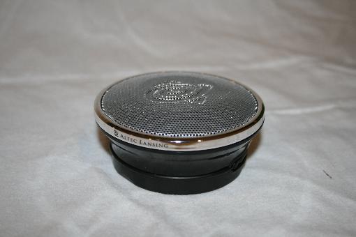
Speaker:
The speaker we used in this project was the Altec Lansing Orbit. We used it for a couple reasons. First off is the sound quality, it absolutely will surprise you with how good it sounds and the bass that it can put out. Secondly the onboard amp that is 5V native. Lastly is the simple interface of a mono phono cable. This allows us to use simple beep output, or complex sounds with a waveshield simply.
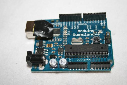
Arduino:
Finally and most importantly the world famous Arduino. This little MCU has been the most fun I have spent 30.00 on that I can remember. Absolutely a must for the tinkerers out there.
So step one here is real easy… glue the box together. If you precisely cut your end pieces the box will more or less be perfectly square and that makes the project a lot easier. Simply glue the components together and let dry. Clamps are recommended but simply turning the box upside down and weighting the top is sufficient.
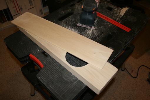
Next up is to sand the box and round off the corners. I used a power sander and it took all of about 5 min as the wood is already prefinished and sanded that I purchased. I also cut a hole to let the sound out and give it the look I was after.
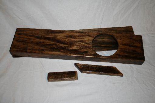
The next step is to stain the project box. We used a dark stain and used 3 coats of a spray on polyurethane to protect the finish and make a nice glassy finish.
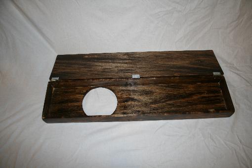
The next step is to attach the hinges to the project box. I highly recommend drilling out the holes to prevent our thin wood from cracking. The screws will likely protrude into the inside of the box, this is just fine and shouldn’t cause alarm.
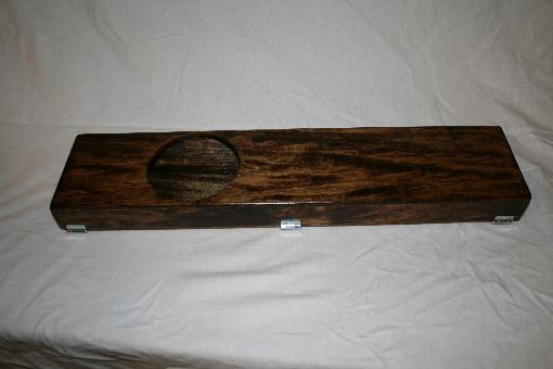
Here we have really the first step in the build finished. It was kinda fun at this point to put the speaker inside the box and turn on an mp3 player hooked up to it to hear the result.

The next step is to mount the electronic mounts on the top of the instrument. This is simple enough of a process of placing them where you want them and then using an awl or a long nail to mark where you will drill the holes at. Once complete use the brass screws and nuts to hold it in place and verify the fit..
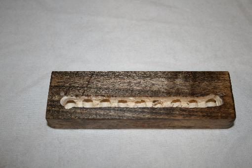
The next step is to drill the bottom out of the stock you are using for the laser emitters and make a channel for the wires to pass. Using a drill press is best to prevent any personal injury.
At the same time we are drilling the holes out for the wires we will also be drilling the holes out for the lasers to mount to. The brass shell of our lasers was about 3/8ths in dia and when we drilled our holes they were quite snug.
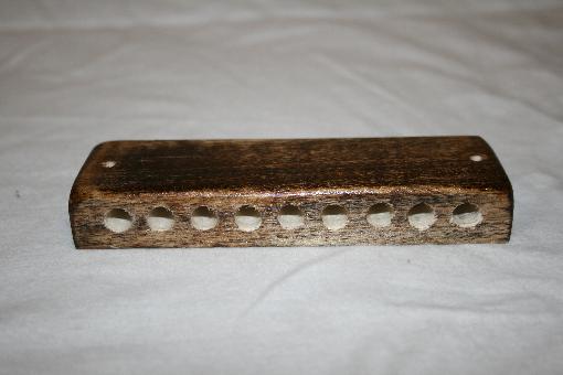
Next we insert our laser modules into the holes we cut. The front half of the laser diode we used was free spinning for the focus of the beam. We simply had to make sure not to push them too far into the hole so that we couldn’t turn them.
Here is another view of the block with the lasers mounted for reference.
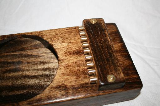
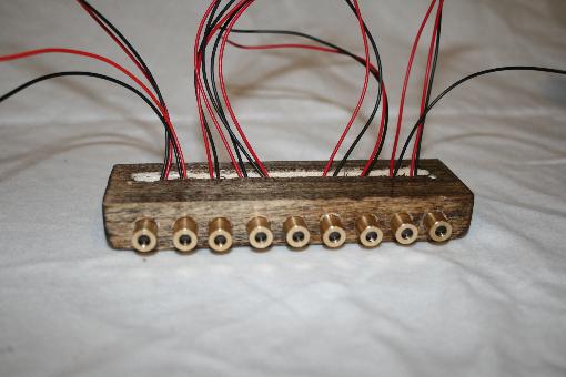
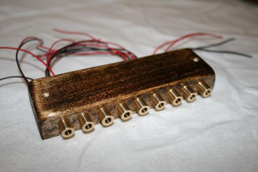
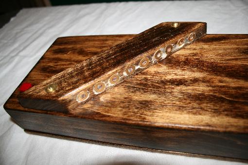
And here we have the finally mounted laser emitter block on the project. It’s actually looking really nice at this point.
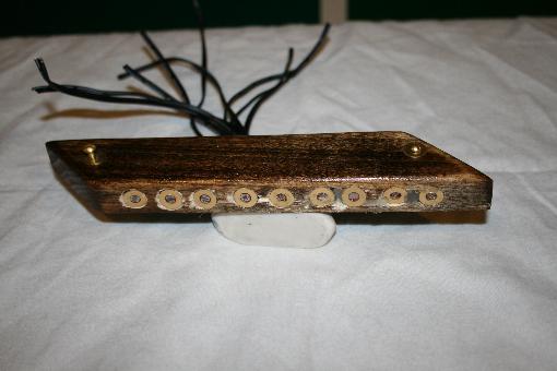
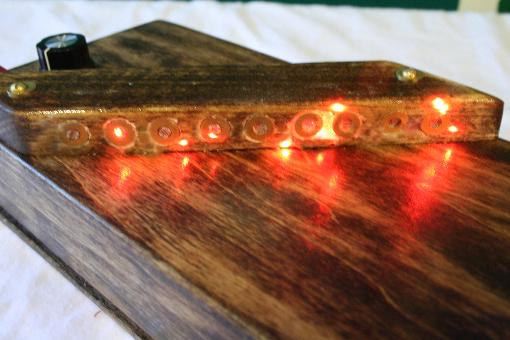
Here we have the upper bar with the CdS mounted. This is very similar to the process for the lower laser bar with the exception that we hot glued the CdS into our brass washers prior to mounting them into the holes. We used some super glue to hold them in place and then filled the remaining cavity with hot glue to insure it would be rugged.
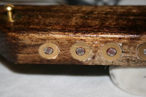
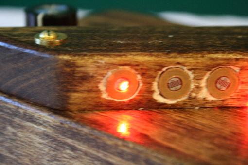
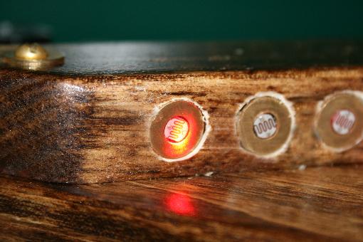
Here is a close up view of the mounts for the CdS and washers.
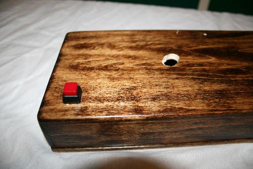
Next with a trial fit and a couple light pencil lines we drilled the hole for the wires in our Cds array to pass into the project box. Its important to do this after the array is completed to make sure your fit is correct. We also drilled a hole and mounted our power button ahead of time to insure a good fit.
Here we have the CdS array bar installed into the bottom of the project base.
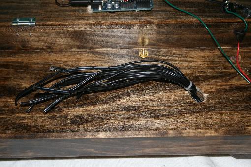
We used a rather generous 12 inch lead from our CdS so we had a good amount to work with and attach to our board. This is more of a comfort thing if you have the extra wire laying around.
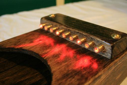
Here we have the test of the laser array and our observation of our alignment for future testing.
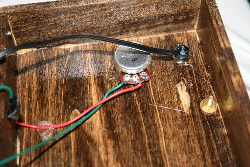
Here we have the lead to our power button and the audio pot for volume control.
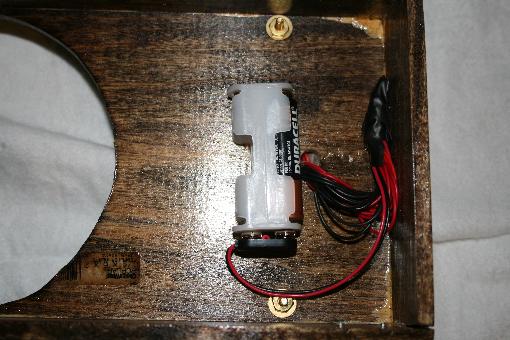
For out laser array I used a separate power source in the end to extend the runtime of the unit dramatically. I simply used some glue to hold it firmly inplace.
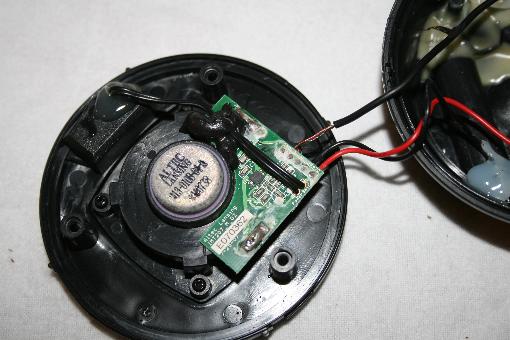
So now onto the modification to the speaker. Basically we are removing all the components we can down to what you see here. This frame contains the speaker amp and power switch. We cut the leads for the power source at the battery pack, and soldered the switch wires together to it is on all the time (when the arduino is on) then applied hot glue to the board bottom to secure the wires in place.
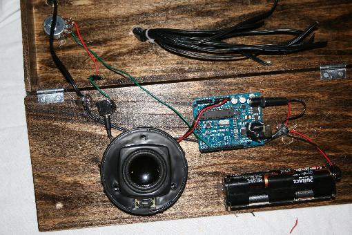
Here we have the beginning of our instrument. We mounted our arduino, speaker and battery pack and connected them. The positive lead to our arduino from the battery pack has our power switch inline, and our speaker is connected to the general ground of the arduino and pin 5 for our beep output.
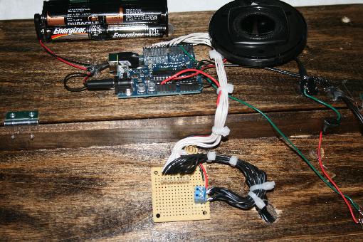
Next we added our breakout board to connect our CdS to our arduino. Has I been thinking I would have bridged the CdS to the common lead inside of the block and not with the giant terminal on our bread board. Oh well… future refinements.
So now with all the hard work done its time to fiddle with the lasers. As you can see while we are very close considering there was no effort for alignment upfront we are actually very close. I found that the misalignment was caused by the lenses inside the laser mounts them self’s. After opening one of the lasers I found the plastic lenses had a small burr on them from being manufactured. Using a razor and a steady hand I was able to fix the alignment issue. A tip to save trouble here is get lasers with glass lenses.
With the lenses fixed and a very slight tweak to the lasers position we have our laser hitting the mark. The dot is very small and it is important to get this as close to center as possible.
With the laser centered we then will intentionally unfocused the laser. Yep! That’s right unfocused. Basically we need to make the dot bigger to get the best coverage on our sensor.
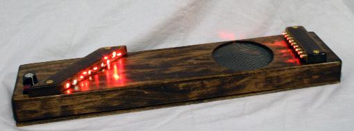
So here we have our finished project. I forgot to mention that I added some screen to the hole as a finishing touch to make the appearance polished. With this basic setup we have reviewed here there is a good deal of extension of features you can do. I recommend the wave shield for arduino as well as midi output (its actually very easy) as great places to start. Also, we used 9 lasers yet there are 8 notes. I used this 9th laser for an octave shift, but it could be used for many different things from sustaining a note to instrument changing…. Really there is a ton of options and as usual we encourage you to experiment.
Related Posts


2 Comments
Hello I really like what you’ve done with this and want to make one myself
but i only dealt with soldering LED lights together and i feel like you’re missing some of the information if I where to build it? Maybe you can email me with more throughout deails? i would really love that
Your welcome to ask any questions here… I am not sure what details your looking for.